Riello RDB 3.2 BT 50/70 Installation, Use And Maintenance Instructions Download Page 29

27 

20148107

GB

Start-up, calibration and operation of the burner

8.12 Programming menu

The programming menu can only be accessed via the reset push-
button or the remote reset during OPERATION.
If  in  page  menu  the  reset  push-button  is  not  pressed,  after  10
seconds occur automatic exit and there is a green led blinking for
the value set.

If the number of pressures on the push-button exceeds the max-
imum allowable, the value in memory will remain the maximum
one.
If the push-button or remote reset is pressed for more than 60
seconds, a failure of the push-button will be visualised and the
control-box will restart.

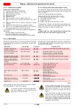
BLOCK DIAGRAM FOR ENTERING THE MENU

Tab. H

8.12.1 Shut-down test

Sequence for shut-down test

Programming allowed in OPERATION.

Press the button for 5 sec. 

 t < 10 sec.

The RED LED blinks twice (0.2 sec. ON; 0.2 sec. OFF)

Release the button 

The burner will initialise a shut-down followed by a restart

After shut-down, the burner restarts automatically and the num-
ber of recycling attempts is restored.
At the exit of shut-down test page menu there are no leds flash-
ing.

8.12.2 Light diagnosis

Sequence for enable/disable

Programming allowed in OPERATION.

Press the button for 15 sec. 

 t < 20 sec.

GREEN led flashing 2 times

Release the button 

GREEN led OFF 

Press push-button 1 time for enable or 2 times for disable

function 

(*)

GREEN led ON and OFF at every press and release

After 10 sec., the GREEN LED will blink for the number of

times programmed (0.5 sec. ON; 0.5 sec. OFF).

Function

Button release 
time

No. of Led 
blinks per 
menu page

No. of pressings of the 
reset push-button

No. of Led blinks 
(green)

Quitting the menu

shut-down test

5s 

 t < 10s

2 blinks
RED

/
none

/
none

Automatic, at the
end of the blinking

Light diagnosis

15s 

 t < 20s

2 blinks
GREEN

1 = enabled 
2 = disabled (default)

1 blink
2 blink

10 sec. after the release of 
the button

Intermittent 
operation 

20s 

 t < 25s

3 blinks
GREEN

1 = 0 disabled
2 = 1 hour 
3 = 24 hours (default)

1 blink
2 blink
3 blink

10 sec. after the release of 
the button

Last lockout 
memorised

25s 

 t < 30s

4 blinks
GREEN

/
none

Displaying the type 
of lockout accord-
ing to the table sec-
tion 8.10.2

10 sec. after the release of 
the button

OPERATION (WITH FLAME)

SWITCHING OFF 

INTERMITTENT

OPERATION

2 RED

2 GREEN

3 GREEN

AUTOMATIC

         OUTLET

10 SEC. AFTER

RELEASE

10 SEC. AFTER

RELEASE

TEST

BRIGHTNESS

DIAGNOSIS

 20 SECS.

LAST LOCKOUT

MEMORISED

 25 SECS.

4 GREEN

10 SEC. AFTER

RELEASE

S9155

5 SECS. 

15 SEC.

BURNER STATE

TYPE OF 
FUNCTION

NUMBER 

OUTLET

OF BLINKS

Fig. 20

Summary of Contents for RDB 3.2 BT 50/70

Page 1: ...20148107 2 07 2018 Installation use and maintenance instructions Kerosene burner One stage operation CODE MODEL 20138275 RDB 3 2 BT 50 70 GB...

Page 2: ...Original instructions...

Page 3: ...for the installation 11 5 2 Handling 11 5 3 Preliminary checks 11 5 4 Installer Servicer notes for the use of Gas oil with Bio blends up to 30 where gas oil use is permitted by the appliance Manufact...

Page 4: ...8 10 12External lockout indicator 26 8 10 13Frequency main supply anomaly 26 8 10 14Internal voltage anomaly 26 8 10 15Checking the fan motor 26 8 10 16Checking the electronic circuit controlling the...

Page 5: ...owing Technical Standard EN 12100 EN 267 and according to the European Directives MD 2006 42 EC Machine Directive LVD 2014 35 UE Low Voltage Directive EMC 2014 30 UE Electromagnetic Compatibility The...

Page 6: ...ed out correctly may cause damage to the ma chine and or injury to people DANGER DANGER LIVE COMPONENTS This symbol indicates operations which if not car ried out correctly lead to electric shocks wit...

Page 7: ...onents most likely to be subject to wear and tear use of non original components including spare parts kits accessories and optional force majeure The manufacturer furthermore declines any and every r...

Page 8: ...ilter of 60 Microns protecting the burner from con tamination If an existing oil storage tank is to be used then in addition to the materials checks as detailed above it will be essential that the tan...

Page 9: ...burner components is not allowed apart from the parts requiring maintenance Only those parts envisaged by the manufacturer can be replaced 3 2 Safety warnings The dimension of the boiler s combustion...

Page 10: ...nel must not carry out on their own initiative opera tions or interventions that are not within their province Personnel must inform their superiors of every problem or dangerous situation that may ar...

Page 11: ...mper adjustment screw 4 Technical description of the burner Designation Voltage Code RDB 3 2 BT 50 70 1 230V 50Hz 20138275 Output Thermal power with air at 20 C 5 0 kg h 60 kW Fuel Kerosene viscosity...

Page 12: ...set for Kerosene use are not suitable for use with Gas oil containing a Bio blend Please refer to the spare part list for the specific hoses suitable for bio fuel use In case of use with gas oil cont...

Page 13: ...he laws in force WARNING The handling operations for the burner can be highly dangerous if not carried out with the great est attention keep any unauthorised people at a distance check the integrity a...

Page 14: ...at the tank and a secondary 60 micron filter are used to protect the burner pump and nozzle from con tamination The burner hydraulic components and flexible oil lines must be suitable for bio fuel use...

Page 15: ...ry the insulating gasket holes 5 see Fig 5 Fix the flange 1 Fig 6 to the boiler door 4 using screws 2 and if necessary the nuts 3 interposing the insulating gas ket 5 Prepare a suitable lifting system...

Page 16: ...e flues for pressure exhaust of flue gases the condensation kind Make sure the air intake tube s inlet is positioned so that it is not likely to be obstructed by foreign matter and where nec essary us...

Page 17: ...ated fuel is returned to the tank If this cannot be avoided make sure that the return pipe is normally below the surface of the fuel level within the storage tank See Fig 12 WARNING The suction plug 1...

Page 18: ...length of the suction line I D internal diameter of the oil pipes NOTE The Tab C and Tab D show the maximum approximate lengths for the supply line depending on the difference in level length and the...

Page 19: ...L max length of the suction line I D internal diameter of the oil pipes NOTE The Tab E shows the maximum approximate lengths for the sup ply line depending on the difference in level length and the d...

Page 20: ...ssure switch ensures the stopping of the burner If this is not the case it is necessary to apply in series with L N a timer switch that turns off the burner at least once every twenty four hours Refer...

Page 21: ...ALLER CARRIED OUT IN THE FACTORY Fig 4 WARNING Do not invert the neutral with the phase in the electrical supply line Check that the electrical supply of the burner corresponds to that shown on the id...

Page 22: ...nel as indicated in this manual and in compliance with the standards and regula tions of the laws in force WARNING Check the correct working of the adjustment com mand and safety devices WARNING Combu...

Page 23: ...chamber with zero depression This regulation is purely indica tive Each installation however has its own unpredictable working conditions actual nozzle output positive or negative pressure in the com...

Page 24: ...ume of air entering the combus tion chamber and thus diminishing its pressure There is a reduction of CO2 and the adhesion of the flame to the air dif fuser disc improves Setting advisable for ignitio...

Page 25: ...ailure t5i Post ignition time Only 3 consecutive re ignition attempts are permitted Loss of flame during operation R ecycle max 3 attempts t1 t3 t4i ts t5i t4l HT FM ID V1 F LED F LED P M t3i POW ERSU...

Page 26: ...complete start up sequence if there is a flame failure during operation the final action at the last attempt following flame failure is a lock out 3 re cycles Status Reset push button colour Seconds C...

Page 27: ...f the parasite flame or the extraneous light are detected during the pre purging the pre purging time of 15 seconds is reset and the time for checking for the presence of a parasite flame or ex traneo...

Page 28: ...see section 8 10 2 8 10 16 Checking the electronic circuit controlling the oil valve The control box detects the presence of a fault inside the elec tronic circuit controlling the oil valve the fault...

Page 29: ...rogramming allowed in OPERATION Press the button for 15 sec t 20 sec GREEN led flashing 2 times Release the button GREEN led OFF Press push button 1 time for enable or 2 times for disable function GRE...

Page 30: ...listed in the table below Tab I Blinking frequency of the reset push button for status indication See Faults diagnosis lockouts on page 24 Description Lockout time Led colour Probable cause Presence o...

Page 31: ...a pump vacuum gauge will assist in this This measure permits the cause of the anomaly to be traced to either the suc tion line or the pump If the problem lies in the suction line check to make sure t...

Page 32: ...nents The safety components must be replaced at the end of their life cycle indicated in Tab J The specified life cycles do not refer to the warranty terms indicated in the delivery or payment conditi...

Page 33: ...interventions must only be carried out by qualified authorised personnel in accordance with the contents of this manual and in compliance with the standards and regulations of current laws Faults Poss...

Page 34: ......

Page 35: ......

Page 36: ...Subject to modifications RIELLO S p A I 37045 Legnago VR Tel 39 0442 630111 http www riello it http www riello com...

Reviews: