background image

2374

4

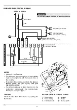
BURNER ELECTRICAL WIRING

S7029

Brown

Wh

ite (5

0V

)

Blue

Motor

Capacitor

Regulating thermostat

Neutr

a

l

Main switch

T6A

N

L

M

~

Black

NOTES

– Wires of  1 mm

2

 section.

– The electrical wiring carried out by the installer

must be in compliance with the rules in force in
the Country.

– To remove the control-box from the burner,

loosen screw (A) (see figure) and pull
towards the arrow.

– The photoresistance is fitted directly into the

control-box 

(underneath the ignition-trans-

former)

 on a plug-in support.

TESTING

Check the shut-down of the burner by opening the
thermostats.

C

ARRIED-OU

T

 IN TH

FACTORY

WARNING

Do not exchange the neutral with the phase.

230V

~

50Hz

N

L

Limit thermostat
with manual resetting

Remote lock-out lamp
(230V - 0.5A max.), if required

1

2

3

4

5

6

7

8

9

Blue

Brown

Terminal block of
control-box 

530SE

*

Valve

T

T

RUN OF THE ELECTRICAL CABLE

1

  - Cable gland

N

 - Neutral

2

  - Cable clamp

L

 - Phase

3

  - Terminal block

- Burner-earth

D5228

Black

Summary of Contents for R40 G7 140-160

Page 1: ...Installation use and maintenance instructions 2902374 5 06 2015 Light oil and kerosene burners One stage operation CODE MODEL TYPE 3745959 R40 G7 140 160 459T55 3745961 R40 G7 160 200 459T55 GB...

Page 2: ......

Page 3: ...Single phase 230V 10 50Hz Motor Run current 0 85A 2850 rpm 298 rad s Capacitor 4 F Ignition transformer Secondary 8 kV 16 mA Pump Maximum pressure 14 bar 203 psi Absorbed electrical power 0 16 kW 1 Re...

Page 4: ...11 204 D5235 189 83 83 170 4 5 It is necessary that the insulating gasket 7 fig 1 is placed between the boiler door and the burner flange This insulating gasket has six holes which if necessary can be...

Page 5: ...flexible pipes conditions Using kerosene they have to be replaced at least every 2 years O A metal bowl filter with replaceable micronic filter must be fitted in the oil supply pipe PRIMING THE PUMP...

Page 6: ...arrow The photoresistance is fitted directly into the control box underneath the ignition trans former on a plug in support TESTING Check the shut down of the burner by opening the thermostats CARRIE...

Page 7: ...on chamber FUEL LIGHT OIL FUEL KEROSENE NOZZLES RECOMMENDED Monarch type R NS Delavan type W A E Steinen type Q H Danfoss type S B H Nozzle Pump pressure Burner output Comb head adjustment Air damper...

Page 8: ...ative Each installation however has its own unpredictable working conditions actu al nozzle output positive or negative pressure in the combustion chamber the need of excess air etc All these conditio...

Page 9: ...et point further ahead than indicated in the instructions Example the instructions require to set the combustion head on set point 3 Instead the setting is made on set point 4 4 FAN AIR DAMPER ADJUSTM...

Page 10: ......

Page 11: ......

Page 12: ...Subject to modifications RIELLO S p A I 37045 Legnago VR Tel 39 0442 630111 http www riello it http www riello com...

Reviews: