background image

20094575

12 

GB

Technical description of the burner

3.11

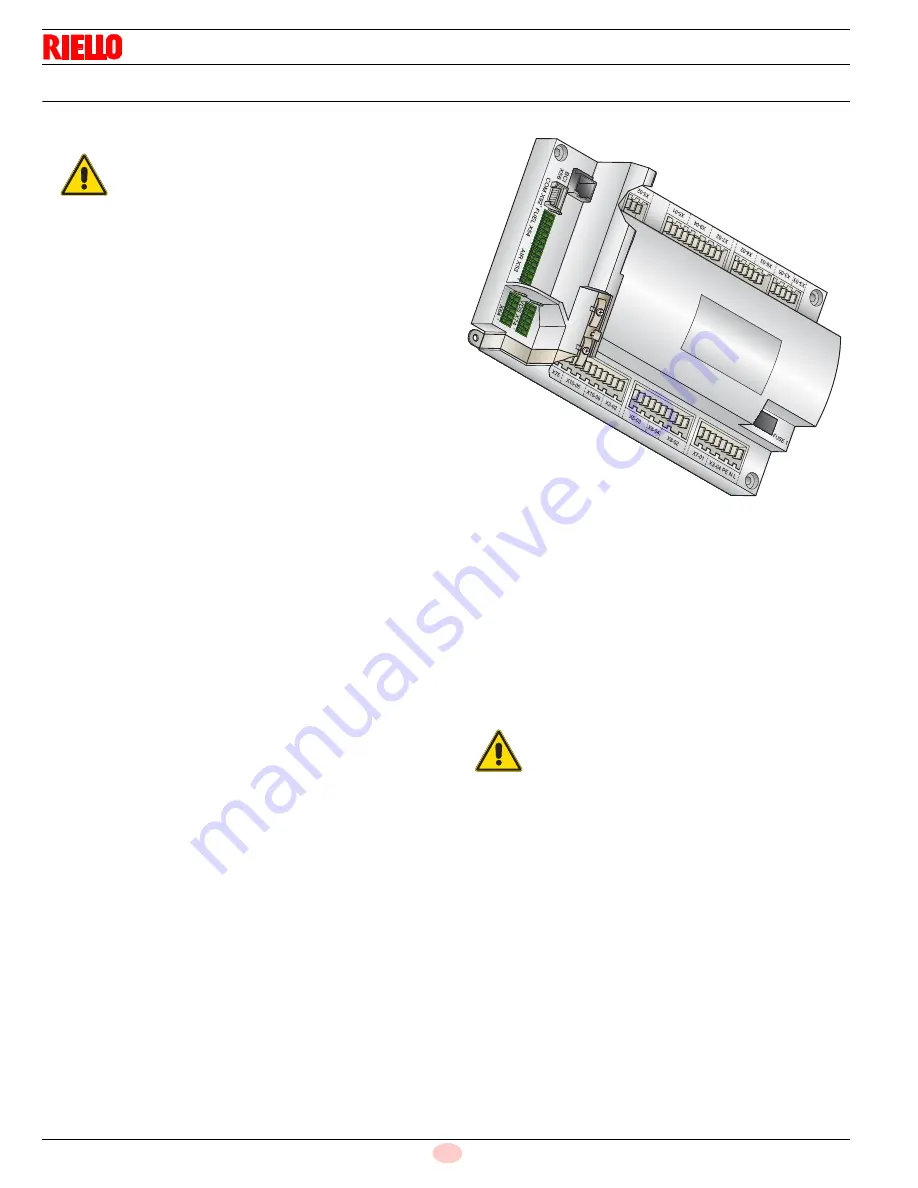
Control box for the air/fuel ratio (LMV37.4...)

Warning notes

All activities (mounting, installation and service work, etc.)
must be performed by qualified staff.

Before making any wiring changes in the connection area,
completely isolate the plant from mains supply (all-polar dis-
connection). Ensure that the plant cannot be inadvertently
switched on again and that it is indeed dead. If not observed,
there is a risk of electric shock hazard.

Ensure protection against electric shock hazard by providing
adequate protection for the burner control’s connection termi-
nals.

Each time work has been carried out (mounting, installation,
service work, etc.), check to ensure that wiring and parame-
ters is in an orderly state.

Fall or shock can adversely affect the safety functions. Such
units must not be put into operation, even if they do not exhibit
any damage.

Introduction

The control box for the air/fuel ratio (Fig. 6), (hereafter referred to
simply as the control box), that equips the burners, carries out a se-
ries of integrated functions in order to optimise burner functioning,
both for single operation and together with other units (e.g. double
furnace boiler or more than one generator at the same time).

The basic functions carried out by the control box relate to:

flame control;

the dosage of air and fuel via the positioning (with direct servo-
control) of the relative valves, excluding the possible play in
the mechanical cam calibration systems;

the modulation of burner output, on the basis of the load
requested by the system, maintaining the pressure or temper-
ature of the boiler at the working values set;

the safety diagnostic of the air and fuel circuits, via which it is
possible to easily identify any causes of malfunctioning.

Mechanical design

The following system components are integrated in the LMV37.4...
basic unit: 

Burner control with gas valve proving system 

Electronic air / fuel ratio control 

Control frequency converter air fan 

Modbus interface 

Installation notes

Always run high-voltage ignition cables separately while ob-
serving the greatest possible distance to the unit and to other
cables.

Do not mix up live and neutral conductors (fire hazard, danger-
ous failures, loss of protection against electric shock hazard,
etc.).

Do not lay the connecting cable from the LMV37.4... to the
AZL2… together with other cables.

Electrical connection of the flame detectors

It is important to achieve practically disturbance- and loss-free sig-
nal transmission:

Never run the detector cable together with other cables.
– Line capacitance reduces the magnitude of the flame signal.
– Use a separate cable.

Observe the maximum permissible detector cable lengths.

The ionization probe is not protected against electric shock
hazard. It is mainspowered and must be protected against ac-
cidental contact.

Locate the ignition electrode and the ionization probe such that
the ignition spark cannot arc over to the ionization probe (risk
of electrical overloads).

WARNING

To avoid injury to persons, damage to property
or the environment, the following warning notes
must be observed!

The LMV37.4... is a safety device! 
Do not open, interfere with or modify the unit.

Riello S.p.A. will not assume responsibility for
any damage resulting from unauthorized inter-
ference!

WARNING

The first start-up, like every further operation for
the internal settings of the control box, requires
access by means of a password and is only to
be carried out by personnel of the Technical As-
sistance Service who have been specifically
trained in the internal programming of the tool.

Fig. 6

D9300

Summary of Contents for C9327710

Page 1: ...20094575 4 05 2018 Installation use and maintenance instructions Forced draught gas burners Progressive two stage or modulating operation CODE MODEL C9327710 RS 190 EV C9328700 C9328710 RS 250 EV GB ...

Page 2: ...Original instructions ...

Page 3: ... values 328 ft above sea level 68 F 11 3 10 Minimum furnace dimensions 11 3 11 Control box for the air fuel ratio LMV37 4 12 3 12 Actuators SQM33 5 15 4 Installation 16 4 1 Notes on safety for the installation 16 4 2 Handling 16 4 3 Preliminary checks 16 4 4 Operation position 16 4 5 Boiler plate 17 4 6 Securing the burner to the boiler 17 4 7 Electrode positioning 18 4 8 Combustion head adjustmen...

Page 4: ...e switch 31 5 6 Final checks with the burner working 32 6 Maintenance 33 6 1 Notes on safety for the maintenance 33 6 2 Maintenance programme 33 6 2 1 Maintenance frequency 33 6 2 2 Safety test with gas ball valve closed 33 6 2 3 Checking and cleaning 33 6 2 4 Flame signal measurement 34 6 2 5 Safety components 34 6 3 Opening the burner 35 6 4 Closing the burner 35 A Appendix Spare parts 36 B Appe...

Page 5: ...ried out correctly may cause damage to the ma chine and or injury to people DANGER DANGER LIVE COMPONENTS This symbol indicates operations which if not car ried out correctly lead to electric shocks with lethal consequences DANGER FLAMMABLE MATERIAL This symbol indicates the presence of flammable materials DANGER BURNING This symbol indicates the risks of burns due to high temperatures DANGER CRUS...

Page 6: ... of damage to things or injury to peo ple if such damage injury was due to any of the following causes incorrect installation start up use and maintenance of the burner improper incorrect or unreasonable use of the burner intervention of unqualified personnel carrying out of unauthorised modifications on the equipment use of the burner with safety devices that are faulty incorrectly applied and or...

Page 7: ...ith the burner components is not allowed apart from the parts requiring maintenance Only those parts envisaged by the manufacturer can be replaced 2 2 Personnel training The user is the person body or company that has acquired the machine and intends to use it for the specific purpose He is re sponsible for the machine and for the training of the people working around it The user Undertakes to ent...

Page 8: ... Free Field method as per EN 15036 and according to an Accuracy Category 3 measuring accuracy as set out in EN ISO 3746 Firing rate for C ETL Canadian Listing 3 Technical description of the burner Model Code Certification RS 190 EV 20044217 RS 250 EV 20036703 Model RS 190 EV RS 250 EV Output 1 Maximum kW MBtu hr 1420 2542 4845 8673 1387 2941 2674 4732 10034 9122 Minimum kW MBtu hr 522 1781 579 197...

Page 9: ...ircuit power supply V Ph Hz 120 1 60 Main electrical supply 10 V Ph Hz 460 3 60 Fan motor rpm HP V A 3500 7 5 460 9 3 3500 7 5 460 9 3 Ignition transformer V1 V2 I1 I2 120 V 1 X 8 kV 1 6 A 20 mA Electrical power consumption W max 6300 6300 Electrical control circuit coms W 750 Total electrical consumption W 7050 7050 Electrical protection NEMA 1 Model RS 190 EV RS 250 EV Control circuit power supp...

Page 10: ...nt The burner is supplied complete with Gas train flange No 1 Flange gasket No 1 Connector for pilot line No 1 Screws M10 x 40 to fix the flange No 4 Washer for screws No 4 Screws M4 x 7 No 2 Disc No 1 Small disc No 1 Instruction manual No 1 Model Code RBNA code Main Voltage Flame safeguard RS 190 EV 20044217 tbd 208 220 3 60 Burner mounted C9327710 460 3 60 tbd 575 3 60 RS 250 EV 20036703 C932870...

Page 11: ...oupling 27 LOCAL REMOTE switch 28 Gas butterfly valve 29 Boiler fixing flange 30 Flame stability disc 31 Horn 32 ALARM SILENCE button 33 POWER ON signal 34 IGNITION ON signal 35 FUEL ON signal 36 ALARM ON signal 37 RWF 55 modulator with analog output 4 20 mA 38 Hight voltage lead 39 Din bar for K7 relay and available for accessories 40 Optional holes 41 Din bar for fuse holder step down transforme...

Page 12: ...han the minimum limit of the diagrams WARNING The firing rate was obtained considering a room temperature of 68 F and an atmospheric pressure of 394 WC approx 0 ft above sea level with the combustion head adjusted Fig 4 Pressure in combustion chamber wc D2431 A RS 190 EV D9093 Pressure in combustion chamber wc Firing rate for C ETL Canadian Listing A RS 250 EV ...

Page 13: ...g 5 indicates the diameter and length of the test combustion chamber Example Output 6400 Mbtu hr diameter 31 5 inch length 10 4 ft AIR TEMPERATURE Altitude Altitude bar press bar press 0 5 10 15 20 25 30 40 C ft a s l m a s l w c mbar 32 41 50 59 68 77 86 104 F 0 0 399 1013 00 1 087 1 068 1 049 1 031 1 013 0 996 0 980 0 948 328 100 394 1000 00 1 073 1 054 1 035 1 017 1 000 0 983 0 967 0 936 1 000 ...

Page 14: ...rcuits via which it is possible to easily identify any causes of malfunctioning Mechanical design The following system components are integrated in the LMV37 4 basic unit Burner control with gas valve proving system Electronic air fuel ratio control Control frequency converter air fan Modbus interface Installation notes Always run high voltage ignition cables separately while ob serving the greate...

Page 15: ...l voltage Nominal current Power factor AC 120 V 50 60 Hz 1 6 A pilot duty load declaration to UL372 cos 0 4 Alarm output Nominal voltage Nominal current Power factor AC 120 V 50 60 Hz 1 A cos 0 4 Ignition transformer Nominal voltage Nominal current Power factor AC 120 V 50 60 Hz 1 6 A pilot duty load declaration to UL372 or 250 VA ignition load declaration to UL372 cos 0 2 Fuel valves Nominal volt...

Page 16: ...P T P 10 Shutdown Operation Startup Valve proving OUTPUTS INPUTS Phase number Fuel Actuator 2 Air Actuator 1 Actuators Safety limit thermostat STB Control thermostat or pressurestat R Flame signal FS Air pressure switch LP Pressure switch min Pmin Pressure switch max Pmax Valve proving leakage test P LT POC alternative to Pmax No load position Ignition load Postpurge position Nominal load Low fire...

Page 17: ...tors can be seen on the dis play of the Operator Panel Index 0 for fuel actuator index 1 for air actuator Installation notes Always run the high voltage ignition cables separate from the unit and other cables while observing the greatest possible dis tance The holding torque is reduced when the actuator is disconnect ed from power Technical data WARNING To avoid injury to persons damage to propert...

Page 18: ...ce WARNING The handling operations for the burner can be high ly dangerous if not carried out with the greatest at tention keep any unauthorised people at a distance check the integrity and suitableness of the available means of handling Check also that the area in which you are working is empty and that there is an adequate escape area i e a free safe area to which you can quickly move if the bur...

Page 19: ...ers with a water cooled frontal a refractory lining is not necessary 11 12 Fig 11 unless expressly requested by the boiler manufacturer 4 6 Securing the burner to the boiler Secure the burner to the boiler fixing the flange 9 Fig 11 to the boiler plate and interposing the insulating gasket 8 Use the 4 screws supplied with a tightening torque of 26 29 Lbf ft after protecting their thread with anti ...

Page 20: ...o sliding bars 5 install the extensions 15 and re screw the screws 2 remove the two screws 4 pull back the burner on the sliding bars 5 of about 4 disconnect the electrode lead then unthread the burner com pletely from the sliding bars remove the screw 1 Fig 13 and extract the inner part 2 of the head check the correct position of ignition electrode as shown in Fig 12 Re install all components wit...

Page 21: ...ge 4 8 2 Gas adjustment When the burner is working at the maximum output 5680 MBtu hr fit the discs 1 and 2 Fig 16 supplied as part of the standard equipment removing the internal tube 3 Fig 16 If the mains gas pressure is low the head can be left in the stand ard set up limiting the modulation minimum to 1970 MBtu hr Example Burner output 6000 MBtu hr The diagram of Fig 14 shows that the adjustme...

Page 22: ...shown in Fig 18 unscrew the 2 screws 2 from the extension 5 and reposition them as previously Fig 18 refit the screws 2 on the sliding bars 3 fix the burner to the pipe coupling with the screws 1 Key Fig 17 and Fig 18 1 Screws 2 Screws 3 Sliding bars 4 Pipe coupling 5 Extension sliding bars 6 Lifting rings WARNING When fitting the burner on the two sliding bars it is advisable to gently draw out t...

Page 23: ...head within the safety time of 3s Ensure that the maximum pressure necessary for the burner is included in the calibration field of the pressure regulator col our of the spring 4 9 2 Gas feeding line It must be type approved according to required standards and is supplied separately from the burner Key Fig 20 1 Gas input pipe 2 Manual valve 3 Pressure regulator 4 Minimum gas pressure switch 5 1st ...

Page 24: ...he diagram Fig 21 and Fig 22 show minimum load losses at combustion head depending on the maximum burner output oper ation with natural gas G 20 Fig 21 Burner output operation D3190 p WC RS 190 EV Fig 22 Burner output operation D10473 p WC RS 250 EV ...

Page 25: ...e required gas pressure at test point 1 Fig 23 set the maximum output required from the burner operation then find the nearest output value in the table for the burner in ques tion read on the diagrams Fig 21 and Fig 22 the pressure test point 1 Fig 23 add this value to the estimated pressure in the combustion chamber Example RS 250 EV Maximum output required 8500 MBtu hr Ring nut 2 Fig 15 adjuste...

Page 26: ...cations or connections different from those shown in the electri cal layouts Check that the electrical supply of the burner corresponds to that shown on the identification label and in this manual Do not invert the neutral with the phase in the electrical supply line Any inversion would cause a lockout due to firing failure The electrical safety of the device is obtained only when it is correctly ...

Page 27: ... 1 Motor cable power supply coming from the inverter 2 Single phase supply cable 3 Connection cable between the inverter and the electronic cam LMV37 WARNING It is very important to shield the motor cable 1 as shown in Fig 25 It is very important to fix the cable shielding as shown in Fig 25 3 2 1 Fig 25 20097545 ...

Page 28: ... the case of clamp type B pull the indicated tabs upwards and lift until locked in the open position B1 Fig 26 insert the shielded cable with the shielding inside the clamp B2 put pressure on the indicated part until the clamp closes auto matically on the shielding B3 4 10 2 Speed sensor adjustment WARNING Do not overtighten B1 A B B2 A1 A2 B3 A3 Fig 26 20131950 WARNING The measurement of speed se...

Page 29: ...clamping the cable to the earth plate The screen must be earthed on both side of the cable take care for good earthing system Examples Number 1 2 3 show not proper ways to earth a cable screen WARNING Following it is reported an example how to con nect the Inverter For further information please refer to the relevant Inverter instruction manual L1 L2 N PE 3 M U PE L1 L2 VWPE PE Fig 28 S8203 Ground...

Page 30: ...tors manufactured for 208 230 460 IE3 NEMA Premium Efficiency voltage have the same connection than IE2 Epact motors but differ ent connection than IE1 motors no more star delta but star double star D3686 IE1 IE2 Epact IE3 NEMA Premium Efficiency U2 V2 W2 U3 V3 W3 U1 V1 W1 S8379 U2 V2 W2 U3 V3 W3 U1 V1 W1 S8380 460V 208 230V 460V 208 230V Fig 31 WARNING the motors manufactured for 575V IE3 NEMA Pr...

Page 31: ...NG The first start up of the burner must be carried out by qualified personnel as indicated in this manual and in compliance with the standards and regula tions of the laws in force WARNING Check the correct working of the adjustment com mand and safety devices WARNING Refer to paragraph Safety test with gas ball valve closed on page 33 before the first start up CAUTION Before starting up the burn...

Page 32: ...he system includes the following basic functions air and fuels are supplied in correct quantities by positioning the valves by direct servo control thus avoiding the possibility of play typical of systems used for traditional modulating burn ers in which settings are obtained by levers and a mechanical cam burner power is modulated according to the load required by the system while boiler pressure...

Page 33: ... switch Adjust the maximum gas pressure switch Fig 38 after having per formed all other burner adjustments with the maximum gas pres sure switch set to the end of the scale With the burner operating at MAX output reduce the adjustment pressure by slowly turning the adjustment dial anticlockwise until the burner locks out Then turn the dial clockwise by 0 8 WC and repeat burner firing If the burner...

Page 34: ...the minimum end of scale position Rotate the air pressure switch knob to the maximum end of scale position The burner must stop in lockout Switch off the burner and disconnect the voltage Disconnect the minimum gas pressure switch The burner must not start Cover the flame sensor The burner must stop in lockout due to firing failure WARNING Make sure that the mechanical locking systems on the diffe...

Page 35: ...n of the burner requires an analysis of the flue gases Significant differences with respect to the previous measurements indicate the points where more care should be ex ercised during maintenance Combustion head Open the burner and make sure that all components of the com bustion head are in good condition not deformed by the high temperatures free of impurities from the surroundings and cor rect...

Page 36: ...6 2 5 Safety components The safety components must be replaced at the end of their life cycle indicated in Tab G The specified life cycles do not refer to the warranty terms indicated in the delivery or payment conditions Tab G WARNING Be extremely careful while troubleshooting the detector line voltage is present on some of the terminals when power is on Open the master switch to disconnect power...

Page 37: ...screw 6 and extract the inner part 5 of the head 6 4 Closing the burner In order to close the burner re install all components with reverse procedure remove the 2 extensions 9 and re screw the screws 8 on the sliding bars 4 push the burner up to approximately 4 from the pipe coupling reinsert the electrode lead and slide the burner as far as the stop Fix the screws 3 to secure the burner to the co...

Page 38: ...2 63 28 64 1 2 32 65 66 63 64 64 45 16 60 55 58 56 54 41 15 43 26 46 39 38 10 10 36 33 35 52 37 31 10 30 42 5 24 53 6 34 46 39 38 10 10 33 35 69 58 55 56 61 68 54 60 36 16 61 53 RS 190 EV 34 49 9 18 22 20 44 17 19 11 12 23 13 51 40 14 23 25 47 48 59 62 48 48 47 47 7 8 21 29 67 ...

Page 39: ...26 AZL DISPLAY B 18 20010968 ELECTRONIC CAM C 19 20096592 POWER REGULATOR C 20 3013940 CONNECTORS ASSEMBLY C 21 20008598 MOTOR C 22 3014106 FUSE 6 3A A 23 20036017 GREEN SIGNAL LIGHT A 24 3013933 INSPECTION WINDOW 25 20027014 WHITE SIGNAL LIGHT A 26 3013681 SCREW C 27 3003891 CONNECTOR C 28 3014079 SPACER 29 20077530 PLATE 30 3012393 ELECTRODE CONNECTION A 31 3012980 ELECTRODE A 32 20008601 SERVOM...

Page 40: ... BASE 48 20010969 RELAY C 49 3012948 AIR PRESSURE SWITCH A 50 20011454 PLUG 51 20010962 BUTTON 52 3013694 DISC C 53 3012049 SCREW 54 3012639 CONTROL DEVICE 55 3012560 SHUTTER 56 3013698 BRACKET 57 20086579 UV SENSOR 58 3013699 END CONE 59 3020068 RELAY 60 3003322 CONNECTOR 61 3013266 MANIFOLD 61 20011351 MANIFOLD 62 3020071 BASE 63 3013938 DISC 64 3013937 HUB 65 3013939 INDEX 66 3014081 BRACKET 67...

Page 41: ...essories 39 20094575 GB Gas train according to UL Standards B Appendix Accessories WARNING The installer is responsible for the supply and instal lation of any required safety device s not indicated in this manual ...

Page 42: ...O2 Low Fire High Fire Main Power Supply O2 Low Fire High Fire Control Power Supply CO Low Fire High Fire Burner Firing Rate NOX Low Fire High Fire Manifold Pressure Net Stack Temp Low Fire High Fire Pilot Flame Signal Comb Efficiency Low Fire High Fire Low Fire Flame Signal Overfire Draft High Fire Flame Signal CONTROL SETTINGS Operating Setpoint Low Oil Pressure High Limit Setpoint High Oil Press...

Page 43: ......

Page 44: ...BURNERS NORTH AMERICA 35 Pond Park Road http www riello ca 2165 Meadowpine Blvd Hingham Massachusetts Mississauga Ontario U S A 02043 1 800 4 RIELLO Canada L5N 6H6 RIELLO S p A I 37045 Legnago VR Tel 39 0442 630111 http www riello com ...

Reviews: