background image

8

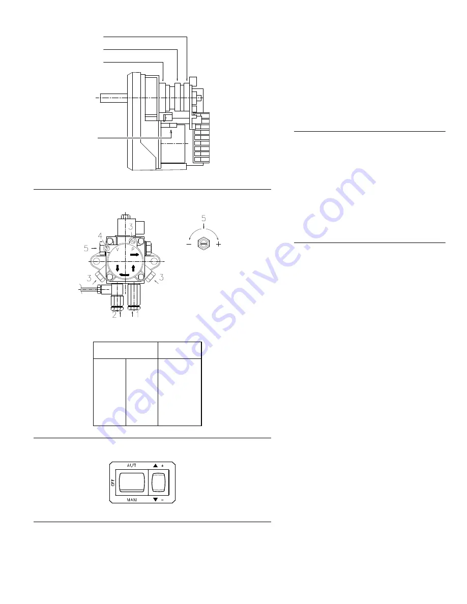
SERVOMOTOR (A)

The servomotor provides simultaneous adjustment of the
air damper 11)(B) page 9 and the pressure regulator 9)
by means of a double variable profile cam, 4) and 7). The
servomotor rotates through 90° in 25 seconds.
Do not alter the factory setting for the cams; simply
check that they are set as indicated below:

Red cam

: 90°

Limits rotation toward maximum position.

Blue cam

: 0°

Limits rotation toward the minimum position. When the
burner is shut down the air damper must be closed: 0°. 

Orange cam

: 15°

Adjusts the ignition position and the MIN output. 

PUMP (B)

1 - Suction

1/4” NPT

2 - Return

1/4” NPT

3 - Pressure gauge attachment G 1/8”
4 - Vacuum gauge attachment

G 1/8”

5 - Pressure adjustment screw

A - Min. delivery rate at 290 PSI pressure
B - Delivery pressure range
C - Max. suction pressure
D - Viscosity range
E - Max fuel oil temperature
F - Max. suction and return pressure
G - Pressure calibration in the factory
H - Filter mesh width

PUMP PRIMING

Before starting the burner, make sure that the tank
return line is not clogged. Obstructions in the line
could cause the seal located on the pump shaft to
break. 

• In order for self-priming to take place, one of the

screws 3)(B) of the pump must be loosened to bleed
off the air contained in the suction line.

• Start the burner by closing the control circuit with

switch 1)(C) in the "MAN" position. As soon as the
burner starts, check the direction of rotation of the fan
blade, by looking through the flame inspection window
19)(A)p.4. 

• The pump can be considered primed when the fuel oil

starts coming out of the screw 3). Stop the burner:
switch 1)(C) set to "OFF" and tighten the screw 3).

The time required for this operation depends upon the
diameter and length of the suction tubing. If the pump
fails to prime at the first cycle of the burner and the
burner locks out, wait approx. 15 seconds, reset the
burner, and then repeat the starting operation as often
as required. After 5 or 6 starting operations allow 2 or 3
minutes for the transformer to cool.  

Important


The priming operation is possible because the pump is
already full of fuel when it leaves the factory. If the pump
has been drained, fill it with fuel through the opening for
the vacuum gauge prior to starting; otherwise, the pump
will seize. Whenever the length of the suction piping
exceeds 66 - 99 ft, the supply line must be filled using a
separate pump.

(C)

(A)

(B)

SUNTEC AL 95 C

D2286

AL 95 C

A
B
C
D
E
F

G
H

GPH

PSI
“Hg

cSt

°F - °C

PSI
PSI

inch

32

145 - 290

13

2 - 12

140 - 60

29

290

0,006

1

2

D791

BLUE CAM

RED CAM

ORANGE CAM

D2522

RESET

Summary of Contents for 9511300

Page 1: ...t oil burners Low high low or modulating operation CODE MODEL C9511300 RL 28 M C9511320 RL 28 M C9512353 RL 38 M C9512300 RL 38 M C9512301 RL 38 M C9512310 RL 38 M C9512320 RL 38 M C9513303 RL 50 M C9...

Page 2: ...Original instructions...

Page 3: ...al and essential part of the product and must not be sepa rated from it it must therefore be kept carefully for any necessary consultation and must accompany the burner even if it is transferred to an...

Page 4: ...d therefore dangerous In particular it can be applied to boilers operating with water steam diathermic oil and to other uses expressly named by the manufacturer the type and pressure of the fuel the v...

Page 5: ...rmal oil Ambient temperature F 32 104 0 40 C Combustion air temperature F max 140 60 C Main power supply 10 V Ph Hz 120 1 60 208 230 460 575 3 60 120 230 1 60 Fan motor rpm W HP V A 3400 370 0 5 120 5...

Page 6: ...on lights up it indi cates that the burner is in lock out To reset press the push button Motor trip RL 38 50 M release by pressing the push button on thermal over load 21 A PACKAGING WEIGHT B Approxim...

Page 7: ...lied with the burner BLAST TUBE LENGTH C The length of the blast tube 7 must be selected accord ing to the indications provided by the manufacturer of the boiler and in any case it must be greater tha...

Page 8: ...ry to change a nozzle with the burner already fitted to the boiler proceed as outlined below Pull back the burner on its slide bars as shown in fig C p 5 Remove the nuts 1 E and the disk 2 Use wrench...

Page 9: ...isted in the Table Key H Pump foot valve height difference L Piping length Inside pipe diameter 1 Burner 2 Pump 3 Filter 4 Manual on off valve 5 Suction line 6 Foot valve 7 Return line HYDRAULIC CONNE...

Page 10: ...B of the pump must be loosened to bleed off the air contained in the suction line Start the burner by closing the control circuit with switch 1 C in the MAN position As soon as the burner starts check...

Page 11: ...H nozzle flow rate Vertical axis PSI nozzle return pressure NOTE With a pump delivery pressure of 290 PSI the pressure on the nozzle return must not exceed 246 5 PSI The pressure difference between pu...

Page 12: ...cam 7 B via the screws 8 Adjusting air delivery Modify the initial profile of the lower cam 4 B via the screws 5 inside the opening 6 If possible do not rotate the first screw as this is the one that...

Page 13: ...ion time short Z connected to terminal 16 t4 Interval between voltage at terminals 18 and 20 t5 Air damper running time to OPEN position t6 Air damper running time to low flame position MIN t7 Permiss...

Page 14: ...PERATION At the end of the starting cycle the servo motor control then passes to load control for boiler pressure or temper ature If the temperature or pressure is low the burner pro gressively increa...

Page 15: ...r limit switch red cam has not been delivered to terminal 8 Terminals 6 7 and 15 remain under voltage until fault has been corrected Lock out Defect in the flame supervision circuit faulty flame signa...

Page 16: ...e combustion head are in good condition positioned correctly free of all impurities and that no deformation has been caused by operation at high temperatures Nozzle Do not clean the nozzle orifices It...

Page 17: ...n Figure below The RL 28 M 38 M 50 M burners have been type approved for intermittent operation This means they should compulsorily be stopped at least once every 24 hours to enable the control box to...

Page 18: ...4 956 Mbtu h AIR TEMPERATURE Altitude Altitude bar press bar press 0 5 10 15 20 25 30 40 C ft a s l m a s l w c mbar 32 41 50 59 68 77 86 104 F 0 0 399 1013 00 1 087 1 068 1 049 1 031 1 013 0 996 0 98...

Page 19: ...17 APPENDIX SPARE PARTS LIST 88 33 42...

Page 20: ...OVER 15 3003766 SCREW 16 3007627 MEMBRAN 17 3012953 SOCKET 18 3007079 SEAL C 19 3013037 CONNECTOR C 20 3012622 DRIVE DISK 21 3012993 MOTOR 120V C 21 3012994 MOTOR 208 230 460V C 21 3013057 MOTOR 575V...

Page 21: ...A 51 3012108 DIFFUSER DISC A 52 3012110 ANCHOR PLATE 53 3012111 HALF SHELL 54 3013016 COIL B 55 3013015 LEAD A 56 3012112 TUBE 57 3012113 TUBE 58 3012114 SHORT SHAFT 59 3012115 LEVER C 60 3012116 BEA...

Page 22: ...12384 OIL PRESSURE SWITCH B 86 3012950 C5360001 CONTROL BOX BASE 87 3013478 SPRING LEVER 02404000001 A 88 20088026 NOZZLE HOLDER C ADVISED PARTS A Spare parts for minimum fittings A B Spare parts for...

Page 23: ...y CO Low Fire High Fire Burner Firing Rate NOX Low Fire High Fire Low Fire Flame Signal Net Stack Temp Low Fire High Fire High Fire Flame Signal Comb Efficiency Low Fire High Fire Low Fire Nozzle Size...

Page 24: ...URNERS NORTH AMERICA 35 Pond Park Road http www riello ca 2165 Meadowpine Blvd Hingham Massachusetts Mississauga Ontario U S A 02043 1 800 4 RIELLO Canada L5N 6H6 RIELLO S p A I 37045 Legnago VR Tel 3...

Reviews: