


35
20146103
GB
Maintenance
Fan
Check that the air damper is positioned correctly.
Check to make sure that no dust has accumulated inside the fan
or on its blades, as this condition will cause a reduction in the air
flow rate and provoke polluting combustion.
Boiler
Clean the boiler as indicated in its accompanying instructions in
order to maintain all the original combustion characteristics in-
tact, especially the flue gas temperature and combustion cham-
ber pressure.
Gas train
Check that the gas train is suited to the burner capacity, the type
of gas used and the mains gas pressure.
Electrode-probe
Checking the proper positioning of the ionisation probe and elec-
trode as shown in Fig. 11 on page 15.
Pressure switches
Check that the air pressure switch and the gas pressure switch
are set correctly.
Gas leaks
Make sure that there are no gas leaks on the pipe between the
gas meter and the burner.
Gas filter
Change the gas filter when it is dirty.
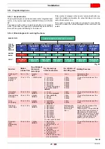
Combustion
If the combustion values measured before starting maintenance
do not comply with applicable legislation or do not indicate effi-
cient combustion, consult the Tab. O on page 33 or contact our
Technical Support Service to implement the necessary adjust-
ments.
Leave the burner working without interruption for 10 min., check-
ing the right settings at 1st and 2nd stage of all the components
stated in this manual.
Then carry out a combustion check verifying:
–
Percentage of CO
2
(%)
–
CO content (ppm)
–
NOx content (ppm)
–
Ionisation current (µA)
–
Smoke temperature at the flue
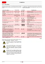
7.2.4
Safety components
The safety components must be replaced at the end of their life
cycle indicated in Tab. P. The specified life cycles do not refer to
the warranty terms indicated in the delivery or payment
conditions.
Tab. P
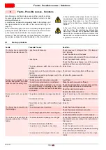
7.3
Opening the burner
If maintenance of the combustion head is required, refer to the in-
structions given in “Operating position” on page 14.
For accessing to the interior of the burner, loosen the screws that
secure the cover and proceed with the maintenance operation.
Check the operation
–
Start-up of the burner with a sequence of functions (see
chapter “Operating programme” on page 22)
–
Ignition device
–
Air pressure switch
–
Flame monitoring
–
Tightness test of components to the passage of fuel
Safety component
Life cycle
Flame control
10 years or 250,000
operation cycles
Flame sensor
10 years or 250,000
operation cycles
Gas valves (solenoid)
10 years or 250,000
operation cycles
Pressure switches
10 years or 250,000
operation cycles
Pressure adjuster
15 years
Servomotor (electronic
cam) (if present)
10 years or 250,000
operation cycles
Oil valve (solenoid)(if
present)
10 years or 250,000
operation cycles
Oil regulator (if present)
10 years or 250,000
operation cycles
Oil pipes/ couplings
(metallic) (if present)
10 years
Flexible hoses (if present)
5 years or 30,000 pressurised
cycles
Fan impeller
10 years or 500,000 start-ups
DANGER
Disconnect the electrical supply from the burner
by means of the main system switch.
DANGER
Turn off the fuel interception tap.
Wait for the components in contact with heat
sources to cool down completely.
DANGER
Operating safety hazards
Repairs to the following components may only be
carried out by the respective manufacturers or by
personnel instructed by them:
–
fan motor
–
actuator
–
air damper servomotor
–
electromagnetic valves
–
burner programmer
After carrying out maintenance, cleaning or
checking operations, reassemble the cover and
all the safety and protection devices of the burner.
Summary of Contents for 40 FS5D
Page 2: ...Translation of the original instructions...
Page 41: ......
Page 42: ......
Page 43: ......


