


20146103
10
GB
Technical description of the burner
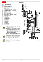
4.8
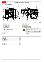
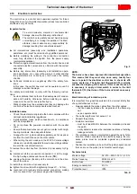
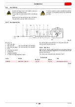
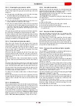
Burner description
1
Air dampers
2
Damper fixing screws
3
Pressure test point (-)
4
Cover fixing screw
5
Air pressure switch
6
Motor
7
Lock-out signal with reset button
8
Control box
9
6 pole socket for gas train
10 Capacitor
11 Gas train elbow
12 Flange
13 Pressure test point (+)
14 Combustion head
15 Electrode-probe
16 Air damper opening motor
17 4-pole socket for 2nd stage
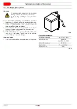
4.9
Burner equipment
Screws with nuts . . . . . . . . . . . . . . . . . . . . . . . . . . . . . . . . No. 4
Insulating gasket . . . . . . . . . . . . . . . . . . . . . . . . . . . . . . . . No. 1
Cover fixing screw . . . . . . . . . . . . . . . . . . . . . . . . . . . . . . . No. 3
Cable grommet. . . . . . . . . . . . . . . . . . . . . . . . . . . . . . . . . . No. 1
Hinge . . . . . . . . . . . . . . . . . . . . . . . . . . . . . . . . . . . . . . . . . No. 1
7-pin plug . . . . . . . . . . . . . . . . . . . . . . . . . . . . . . . . . . . . . . No. 1
4-pin plug . . . . . . . . . . . . . . . . . . . . . . . . . . . . . . . . . . . . . . No. 1
Instructions. . . . . . . . . . . . . . . . . . . . . . . . . . . . . . . . . . . . . No. 6
Spare parts list . . . . . . . . . . . . . . . . . . . . . . . . . . . . . . . . . . No. 1
Fig. 4
20065574
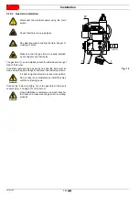
WARNING
The supplied grommet and the cover fixing screw
should be assembled on the same side as the gas
train.
Check that it is possible to access the cover fixing
screws once the burner has been installed. If nec-
essary, replace them with the ones supplied as
standard.
Summary of Contents for 40 FS5D
Page 2: ...Translation of the original instructions...
Page 41: ......
Page 42: ......
Page 43: ......


