


2094
4
GB
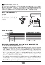
ELECTRICAL WIRING
Bro
wn
White
(50V)
Blue
Motor
Capacitor
Regulating thermostat
Neutr
al
Main switch
T6A
N
L
M
~
S7029
Black
NOTES
– Wires of 1,5 mm
2
section.
– The electrical wiring carried out by the installer
must be in compliance with the rules in force in
the Country.
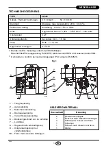
– To remove the control-box from the burner,
loosen screw (A)
(see figure) and pull
towards the arrow.
– The photoresistance is fitted directly into the
control-box
(underneath the ignition-transformer)
on a plug-in support.
TESTING
Check the shut-down of the burner by opening
the thermostats.
CARRIED-OUT IN THE FACTORY
WARNING
DO NOT EXCHANGE THE
230V
~
50Hz
N
L
Limit thermostat
with manual resetting
Remote lock-out lamp
(230V - 0.5A max.), if required
1
2
3
4
5
6
7
8
9
Blue
Bro
wn
Terminal block of
control-box 530SE
*
Valve
T
T
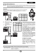
RUN OF THE ELECTRICAL CABLE
1 - Grommet
N - Neutral
2 - Cable-clamp
L - Phase
3 - Terminal block
- Burner-earth
D5228
Black
●
(See page 3). Connect the automatic shut-off
device (230V - 0,5A max.) to the clamps 3 - 6
of control-box.
NEUTRAL WITH THE PHASE.
Summary of Contents for 3452082
Page 2: ......


