


2094
2
GB
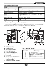
DIMENSIONS
MOUNTING THE BURNER
Flange
Burner
305
104
265
140
=
44
45°
262
11
204
D5397
=
189
83
83
170
45°
ø
105
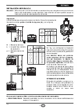
It is necessary that the two insulating
gaskets (10, fig. 1) are placed between
the boiler door and the burner flange.
These insulating gaskets have six holes,
which, if necessary, can be modified as
shown on the drawing on the right.
D5242
Fig. 2
Verify that the installed
burner is lightly leaned
towards the button.
(See figure 2).
The burner is designed to
allow entry of the flexible
oil-lines on either side of
the burner.
D5572
BURNER FIXING AND
HINGE ASSEMBLY
S7385
Summary of Contents for 3452082
Page 2: ......


