9
ENGLISH
WATER CONNECTIONS
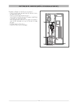
A solenoid valve must be fitted in the incoming cold water pipe of each DHW mixer.
The minimum recommended dimensions for the water pipes connecting the DHW mixers are:
Primary inlet and outlet . . . . . . . . . . . . . . . . . . . . .1 1/4”
Domestic cold water inlet . . . . . . . . . . . . . . . . . . .1 1/4”
Domestic hot water outlet . . . . . . . . . . . . . . . . . . .1 1/4”
Recirculation . . . . . . . . . . . . . . . . . . . . . . . . . . . . .1”
Connecting pipes between the DHW mixers
and the inlet/outlet pipes . . . . . . . . . . . . . . . . . . . .ø18
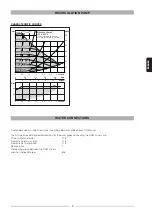
RECIRCULATION PUMP
CHARACTERISTIC CURVES
0
0,5
1,0
1,5
2,0
2,5
3,0
0
0,2
0,4
0,6
0,8
0
2
4
6
8
10
0
1
2
3
4
5
6
7
0
10
20
30
40
50
60
70
0
0,5
1,0
1,5
2,0
2,5
3,0
0
20
40
3695/ 25
PWM1
/ 75
PWM2
4178/ 15
PWM1
/ 85
PWM2
4660/ ≤5
PWM1
/ ≤95
PWM2
3213/ 35
PWM1
/ 65
PWM2
2730/ 45
PWM1
/ 55
PWM2
2248/ 55
PWM1
/ 45
PWM2
1765/ 65
PWM1
/ 35
PWM2
1283/ 75
PWM1
/ 25
PWM2
800/ 85
PWM1
/ 15
PWM2
p/kPa
H/m
P
1
/W
Q/m³/ h
Q/l/s
Q/Igpm
Q/m³/ h
max.
max.
Wilo-Yonos Para Z
15/7.0, 25/7.0
1-230 V - Rp1/2, Rp1, Rp1 1/4
n=1 / min / % PWM 1 / % PWM 2


