background image

4

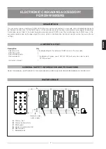
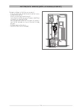
MESSA IN FUNZIONE DEL MODULO CON KIT DI RICIRCOLO

Procedura per il montaggio del kit di ricircolo:

 - Chiudere le valvole a sfera di ingresso AFS (3) e di usci-

ta ACS (4)

 - Svitare e estrarre il tappo 3/4” (1)

 - Inserire il KIT di ricircolo avvitando i componenti e la 

calotta a tenuta

 - Inserire la sonda S1 nel posto indicato (2) e collegarla 

alla centralina, seguendo lo schema elettrico

 - Mettere in pressione il circuito

 - Controllare la tenuta idraulica del circuito

1

2

3

4

Summary of Contents for 20083501

Page 1: ...stita dalla centralina in base alle impostazioni inserite CONTENUTO DELLA CONFEZIONE Descrizione Q t Elettrovalvola 2 3 in base al numero dei moduli in cascata Cavo bus 1 Circolatore ricircolo 1 Kit r...

Page 2: ...limentazione 230Vac 50 60 Hz Classe di protezione IP65 Pressione di esercizio 0 2 15 bar Portata 5 m3 h Temperatura di esercizio 30 145 C DN 18 Tempo di chiusura 1 4 sec T ambiente max 80 C T fluido m...

Page 3: ...lo 1 Tubi di collegamento tra i moduli e i tubi delle linee di mandata ritorno 18 CIRCOLATORE RICIRCOLO CURVE CARATTERISTICHE 0 0 5 1 0 1 5 2 0 2 5 3 0 0 0 2 0 4 0 6 0 8 0 2 4 6 8 10 0 1 2 3 4 5 6 7 0...

Page 4: ...i ingresso AFS 3 e di usci ta ACS 4 Svitare e estrarre il tappo 3 4 1 Inserire il KIT di ricircolo avvitando i componenti e la calotta a tenuta Inserire la sonda S1 nel posto indicato 2 e collegarla a...

Page 5: ...morsettiera metallica PE COLLEGAMENTO ELETTRICO La cascata per i moduli ACS 40 E viene gestita elettronicamente dalla centralina e i moduli sono collegati mediante il collegamento can bus tra le cent...

Page 6: ...off 1 10 secondi 6 sec Inserire i parametri del ricircolo solo nella centralina del modulo dove stato installato il kit di ricircolo Inserire le impostazioni nell ordine presente nella tabella seguent...

Page 7: ...g of this valve which is controlled by the mixer s control unit on the basis of user settings CONTENTS OF KIT Description Qty Solenoid valve 2 3 depending on the number of DHW mixers in the cascade CA...

Page 8: ...supply 230Vac 50 60 Hz Protection class IP65 Operating pressure 0 2 15 bar Flow rate 5 m3 h Operating temperature 30 145 C DN 18 Closing time 1 4 sec Max ambient temperature 80 C Max water temperatur...

Page 9: ...s between the DHW mixers and the inlet outlet pipes 18 RECIRCULATION PUMP CHARACTERISTIC CURVES 0 0 5 1 0 1 5 2 0 2 5 3 0 0 0 2 0 4 0 6 0 8 0 2 4 6 8 10 0 1 2 3 4 5 6 7 0 10 20 30 40 50 60 70 0 0 5 1...

Page 10: ...t wa ter outlet ball valve 4 Unscrew and remove the 3 4 plug 1 Install the recirculation accessory Screw on and fittings and tighten the watertight fitting Insert temperature sensor S1 in its socket 2...

Page 11: ...of ACS 40 E DHW mixers is controlled electronically by the control units The various mixers in the cascade are connected via a CAN bus cable between their control units Unscrew the screw at the botto...

Page 12: ...econds 6 secs Enter the recirculation parameters only in the control unit in which the recirculation kit is installed Enter the settings in the order given in the following table Menu Description Sett...

Reviews: