


- 8 -
PROFIBUS
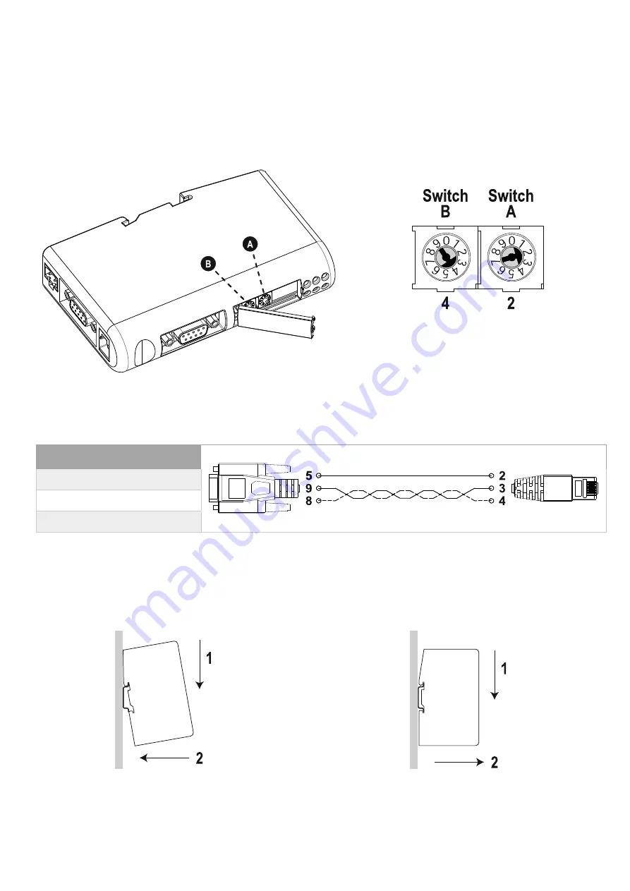
CONFIGURATION SWITCHES
The configuration switches are used to set the PROFIBUS node address. Remove the plastic hatch to configure the switches (see
image below). Note that the node address cannot be changed during runtime, i.e. the gateway requires a reset for changes to have
effect.
The configuration is done using two rotary switches as follows: Node Address = (Switch B x 10) + (Switch A x 1)
Note:
When removing the hatch and configuring the switches, avoid touching the circuit boards and components.
Example:
If the node address should be 42:
set switch A to “2” and switch B to “4”.
C
ONNECTION CABLE
M
ULTI
COM
302
↔
PROFIBUS
DP
G
ATEWAY
DB9 male
PIN
connect
to
RJ-45
PIN
5
↔
2
9
↔
3
8
↔
4
NOTE: Use a twisted pair to connect PIN #9 and #8 of DB9 to PIN #3 and #4 of RJ-45
DIN‐
RAIL MOUNTING
To snap the gateway
on
, first press it downwards (1) to
compress the spring in the DIN-rail mechanism, then push
it against the DIN-rail as to make it snap on (2).
To snap the gateway
off
, push it downwards (1) and pull it out
from the DIN-rail (2), as to make it snap off from the DIN-rail.


