


‐ 78 ‐
BM
REPLACEMENT
The following operations must only be performed by skilled and specifically trained service personnel.
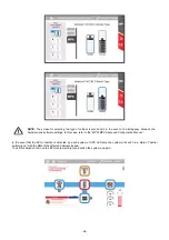
Refer to the Insertion/Extraction procedure
Operation to be performed in order to replace a BM during “Online Mode” status without interrupting power to the load:
Verify that the load is correctly supported by all of the PMs.
Verify that the BM is not supplying the load.
Open the associated switch lock.
Extract the BM (Please note that the BM weighs 23 kg and 2-person handling is required).
Insert a new BM and close its switch lock.
Verify that all the measurements of the new BM are correct on the “System Status” page.
Verify that the operational status of the new BM is “Ready” on the “System Status” page.
R
EPLACING
MU,
MCU,
CP
AND
PSU
The following operations must only be performed by skilled and specifically trained service personnel.
Refer to the Insertion/Extraction procedure
This operation can be performed without interrupting power to the load:
The replacement of these units will not affect the load.
Simply extract the unit and insert the new one.
Verify the status of the replaced unit.
NOTE:
If the MCU or CP is removed the system will continue to operate correctly. During this time the user will only lose the
system monitoring functions.
WARNING:
The MU, MCU and CP must be configured accordingly to the system (refer to the “MPW-MPX Advanced
Configuration Manual” for correct setting).
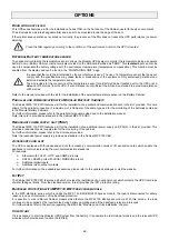
BU
REPLACEMENT
The following operations must only be performed by skilled and specifically trained service personnel.
Refer to the Insertion/Extraction procedure
This operation must only be performed when the SYSTEM IS NOT OPERATING ON BATTERY MODE:
Verify that the MPX is not working in battery mode.
Remove the safety screws and bracket.
Extract the BU (Please note that the BU weighs 32kg and 2-person handling is required).
Reinsert the new BU.
Verify that the SYSTEM is reporting the correct measurements and setup.
Fasten the bracket and all the required screws.
Summary of Contents for MPX 100 CBC
Page 1: ......
Page 2: ......
Page 8: ... 6 Top view Bottom view Display Wheels Bottom cable entry Fastening stands ...
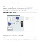
Page 19: ... 17 A wring diagram of the Modular UPS Power Cabinet is provided below ...
Page 22: ... 20 The wiring diagram of the Modular UPS Combo Cabinet is provided below ...
Page 54: ... 52 Combo Cabinet MPX 100 CBC ...
Page 55: ... 53 Battery Cabinet MPW 170 BTC ...
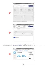
Page 73: ... 71 MONITORING VIA WEB BROWSER ...
Page 91: ......
Page 92: ...0MNMPXK15RUENUB ...