background image


CCP-1116 Commentary Control Panel – Quick Guide 1.2


Page


16


In the “

Key Test

” mode you can test all key-contacts, rotary encoders, encoder switches and LEDs. 

Every  time  you  press  a  button  or  turn  an  encoder,  the  half  side  color  on  the  responsible  OLED-
display will change.  

By turning and pressing the Master volume encoder, the 8 Volume LEDs will change the color. 


To stop the “

Key Test

” mode, you have to reset the panel by pressing 

“Shift”+”F1”+”F2”. 


6.3


Config 

In the “

Config

” menu, you can adjust the default display color and if the panel should be detected 

by the Director as a “DCP-1116” or “CCP-1116”. 

6.3.1


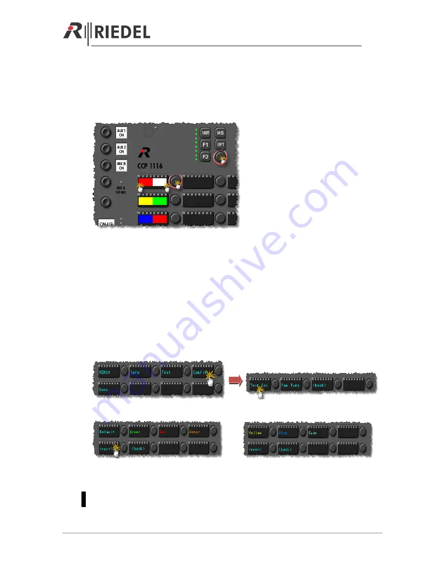
Config: Text Color 

In this menu you can set the default text color. This default color is shown, as long the panel is in 
the “

Wait for

” mode when it is not connected to the matrix. 


Press “

Config

” in the main menu 


Select the color by pressing the desired color button.  


 or


With  “

<back>”

  you  can  go  back  to  the  config  menu.  After  resetting  the  panel,  it  will  show  the 

selected color in the “

Wait for

” mode. 

As soon the panel is connected to an Artist system, the Artist configuration assigns the colors to 
the buttons. 

Summary of Contents for CCP1116

Page 1: ...CCP1116 Quick Guide Commentary Panel Document Reference 1 2 S Franke 01 2013 ...

Page 2: ...r für die Richtigkeit des Inhalts dieses Handbuchs Die Rechte an anderen in diesem Handbuch erwähnten Marken und Produktnamen liegen bei ihren Inhabern und werden hiermit anerkannt 2013 Riedel Communications GmbH Co KG All rights reserved Under the copyright laws this manual may not be copied in whole or in part without the written consent of Riedel Every effort has been made to ensure that the in...

Page 3: ... 6 3 REAR SIDE DIP SWITCHES 7 4 AUDIO BLOCK DIAGRAM 8 5 DIRECTOR CONFIGURATION OF A CCP 1116 9 5 1 Key assignment Commentator A B 10 5 2 GPIO functions 12 5 3 Commentary Audiopatch settings 13 6 PANEL TEST CONFIG MODE 15 6 1 Info 15 6 2 Key Test 15 6 3 Config 16 6 3 1 Config Text Color 16 6 3 2 Pan Type 17 6 4 Demo Mode 17 7 SPECIFICATIONS 18 8 SERVICE 19 9 NOTES 20 ...

Page 4: ...evelmeter you can adjust the listen level 4a MIC A Sidetone Mixes the MIC A signal to the Headphones A depending of the dip settings on the rear side to the left right or both ears With the Dip switch Always you can choose to activate the Sidetone always or only when ON AIR is pressed 4b MIC A Signal LED Indicates green as soon a signal from MIC A is coming into the CCP 1116 LED color changes to o...

Page 5: ...tor B 2 CONNECTORS 2 1 Connectors front side 1 2 3 4 5 6 Nr Function Connector Type Artist Director Pin out 1 PHONES A 6 35mm Stereo Jack Audio Patch Audio OUT A Tip Left Ring Right Sleeve GND 2 MIC A 1 2 3 XLR3 female Audio Patch Audio IN A Pin 1 Shield Pin 2 Signal hot Pin 3 Signal cold 3 HEADSET A INTERCOM only for pure Intercom use 1 2 3 4 XLR4 male Audio Patch Headset A Pin 1 Shield Mic Pin 2...

Page 6: ...N Director GPI IN 3 Pin 5 5V 250mA Shield Ground 4 MATRIX BNC BNC Pin Tx RX Data Shield Tx Rx Data 5 MATRIX CAT5 CAT5 Pin 1 TxD Pin 2 TxD Pin 3 RxD Pin 6 RxD 6 Ext Speaker 1 2 3 XLR3 male Audio Patch Ext OUT Tip Left Ring Right Sleeve GND 7 LINE IN 1 2 3 XLR3 female Audio Patch External MIC only available in Speaker Mode Pin 1 Shield Pin 2 Signal hot Pin 3 Signal cold 8 AUX 1 IN XLR3 female n a Se...

Page 7: ...m signal to left L right R or both ears M 4 PHONES MODE AUX 1 Routes AUX 1 signal to left L right R or both ears M 5 PHONES MODE AUX 2 Routes AUX 2 signal to left L right R or both ears M 6 ALWAYS MIC A Sidetone MIC A Always routed to the phones A or only when ON AIR A is pressed 7 ALWAYS MIC B MIC B signal always routed to the phones or only when ON AIR B is pressed Only works when MIC B ON is ac...

Page 8: ...CCP 1116 Commentary Control Panel Quick Guide 1 2 Page 8 4 AUDIO BLOCK DIAGRAM ...

Page 9: ...o adapt some configuration settings in the Director First you have to create a new CCP 1116 on an odd digital port for 2channel operation and activate enable 2nd Audio channel in the properties of the port Open the Panel view with a double click on the port Hint Up from Director 6 60 the CCP will be created automatically as a 2 channel port when you add it to an odd port and the following port is ...

Page 10: ...mind that on all functions for the Commentator B the 2nd audio channel as source has to be enabled You can find this option in the properties of the audio functions So open the properties of the keys with audio functionality for Commentator B one after the other and enable the 2nd audio channel as source for Call to functions and also as source for Listen to functions When commentator A needs to t...

Page 11: ...fore you have to activate the flag to 2nd channel in the properties of the function It is useful to manually label the key in Com B or similar ATTENTION For the Commentator B there are some limitations at the moment Reply is not working correctly for the Commentator B for the 2nd audio channel It is not possible to use an IFB from the IFB Tabelle for the 2nd Commentator Here you have to configure ...

Page 12: ... to an Intercom destination while he is on air Both GPIOs will be labeled automatically with the panel name and functionality GPIO IN 3 and GPIO OUT 3 are the only ones which can be used individually The GPIO 3 is available on a XLR5 pin connector on the rear side of the CCP 1116 Now you can drag and drop GPO 1 and 2 to all the intercom buttons that are able to activate the microphone of the panel...

Page 13: ...lusive this signal is routed hard wired to the XLR AIR A OUT and AIR A B OUT analog outputs and can be affected by the ON AIR A key AUDIO IN B MIC B XLR 3pol front side The key MIC MUTE B takes effect always on this input signal Exclusive this signal is routed hard wired to the XLR AIR B OUT and AIR A B OUT analog outputs and can be affected by the ON AIR B key Matrix CH 1 Audio channel 1 Commenta...

Page 14: ...a CCP and the basic crosspoints within the Audiopatch are already set as default Hint It is recommended to also add an additional Audiopatch with standard panel settings Gooseneck Microphone Speaker to the Panel This preset can be activated by a Select Audiopatch function for example on the Shift page of the Commentary Panel to activate a standard Intercom audio routing during rehearsals or when t...

Page 15: ...oot the panel Immediately press the F1 button and keep it pressed until the panel has started the Service menu 6 1 Info Press the Info button to show the current installed firmware versions for the front board Press any button to go back to the main menu 6 2 Key Test Press Test to get into the test mode Press Key Test to start the Key Test mode Please do not use the FlashTst it is just for interna...

Page 16: ...ig In the Config menu you can adjust the default display color and if the panel should be detected by the Director as a DCP 1116 or CCP 1116 6 3 1 Config Text Color In this menu you can set the default text color This default color is shown as long the panel is in the Wait for mode when it is not connected to the matrix Press Config in the main menu Select the color by pressing the desired color b...

Page 17: ... the mode to DCP 1116 Also if you get an Alarm message within the Director that a wrong panel type is connected DCP instead of a CCP you have to change the mode to CCP Press the button Pan Type Then press the button with the panel type you want to use After resetting the panel it will log on in the Artist as the assigned type 6 4 Demo Mode By pressing Demo you can start a demo mode where all butto...

Page 18: ...Transformer Impedance 10kΩ Maximum Input Level 18dBu Nominal Input Level 6dBu Input Noise Voltage 73dBu 20Hz 22kHz THD N 0 1 18dBu 1kHz CMRR 60dB 1kHz AUDIO LINE INPUT LINE IN Coupling Transformer Impedance 10kΩ Input Level 10 18dBu Nominal Input Level 6dBu Input Noise Voltage 73dBu 20Hz 22kHz THD N 0 2 0 05 1kHz SNR 91dB AUDIO LINE OUTPUT DIRECT OUT A DIRECT OUT B AIR A OUT AIR B OUT AIR A B OUT ...

Page 19: ... Riedel Customerservice in Wuppertal Germany is always available to help you Telephone 49 0 202 292 9400 Monday Friday 8 00 17 00 Central European Time Fax 49 0 202 292 9419 Skype riedel communications service Or use the contact form on our website www riedel net For repairs please contact your local distributor Your distributor will help you with the repair process and with securing replacement p...

Page 20: ...CCP 1116 Commentary Control Panel Quick Guide 1 2 Page 20 9 NOTES ...

Page 21: ...CCP 1116 Commentary Control Panel Quick Guide 1 2 Page 21 ...

Page 22: ...Page 22 Riedel Communications GmbH Co KG Uellendahler Str 353 42109 Wuppertal Germany Phone 49 0 202 292 90 Fax 49 0 202 292 99 99 sales international riedel net Wuppertal Beijing Berlin London Los Angeles Singapore Sydney Vienna Zurich www riedel net ...

Reviews: