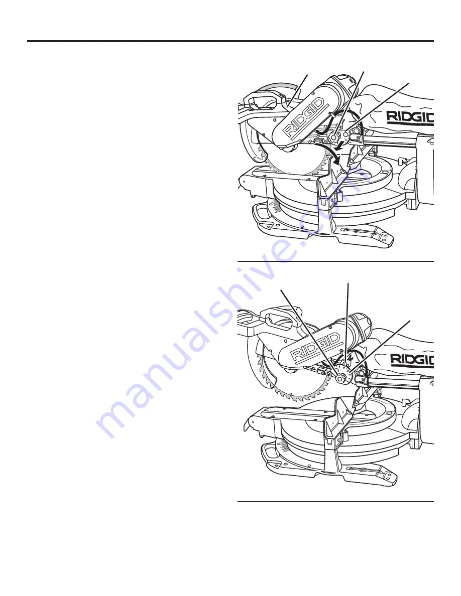
RIDGID MS1290LZA Operator'S Manual Download Page 16

16

ASSEMBLY

Fig. 9

NOTE: 

Many of the illustrations in this manual show only 

portions  of  the  compound  miter  saw.  This  is  intentional 
so  that  we  can  clearly  show  points  being  made  in  the 
illustrations. 

Never  operate  the  saw  without  all  guards 

securely in place and in good operating condition.

LOCKING / UNLOCKING THE SAW ARM

See Figure 9.

When locking and unlocking the saw arm, it is not necessary 
to loosen the depth control knob.

To unlock and raise the saw arm:

  Firmly grasp the “D” handle and apply downward pres-

sure while at the same time pulling the depth guide out 
and away from the saw housing.

  Turn the guide to the right until the flat of the guide is 

facing up.

  Release the guide and slowly raise the saw arm.

To relock the saw arm:

  Firmly grasp the “D” handle and apply downward pressure 

while at the same time pulling the depth guide out and 
away from the saw housing.

  Turn the guide to the left until the hole in the guide is 

positioned over the lock pin.

  Release the guide allowing the lock pin to align with the 

hole

 in the guide.

  Check  that  the  slide  lock  knob  is  locked  in  place  by  

turning the knob clockwise.

USING THE DEPTH GUIDE

See Figure 10.

When used, the depth guide limits the downward travel of the 
blade when cutting dadoes and other non-through cuts.
Make a mark on the lock pin with a pencil for use with the 
scale  on  the  guide.  “A”  on  the  guide  represents  the  saw 
blade teeth being level with the miter table. Each mark on 
the  depth  guide  is  approximately  1/4  in.  Always  make  a 
practice cut on scrap wood. With the flat side of the guide 
facing  up,  the  saw  can  be  used  without  any  interference 
from the guide.

To use the depth guide:

  If the saw is in storage or transport position, unlock the 

saw arm.

  Position the depth guide by turning until it engages the 

internal locking mechanism.

  Loosen  the  depth  control  knob  (turn  knob  counter-

  clockwise).

  Determine the desired depth of cut, set the guide to that 

mark, and retighten the depth control knob (turn knob 
clockwise).

NOTE: 

To override the depth setting, pull the depth gauge 

out and away from the saw housing and turn the guide until 
the flat of the guide is facing up.

Fig. 10

SAW ARM

DEPTH 

GUIDE

DEPTH CONTROL 

KNOB

DEPTH 

GUIDE

LOCK PIN

DEPTH CONTROL 

KNOB

Summary of Contents for MS1290LZA

Page 1: ...high standard for dependability ease of operation and operator safety When properly cared for it will give you years of rugged trouble free performance WARNING To reduce the risk of injury the user m...

Page 2: ...13 Loose Parts 14 Assembly 15 24 Operation 25 35 Adjustments 35 Maintenance 36 37 Accessories 38 Warranty 39 Parts Ordering Service 40 INTRODUCTION This tool has many features for making its use more...

Page 3: ...ain long hair ALWAYS WEAR SAFETY GLASSES WITH SIDE SHIELDS Everyday eyeglasses have only impact resistant lenses they are NOT safety glasses GENERAL SAFETY RULES SECURE WORK Use clamps or a vise to ho...

Page 4: ...UNDER THE INFLUENCE OF DRUGS ALCOHOL OR ANY MEDICATION WHENSERVICINGuse only identical replacement parts Use of any other parts may create a hazard or cause product damage USE ONLY RECOMMENDED ACCESS...

Page 5: ...known to cause cancer birth defects or other reproductive harm Some examples of these chemicals are lead from lead based paints crystalline silica from bricks and cement and other masonry products an...

Page 6: ...peed orbits etc per minute Do not expose to rain or use in damp locations To reduce the risk of injury user must read and understand operator s manual before using this product Eye Protection Precauti...

Page 7: ...which if not avoided may result in minor or moderate injury Without Safety Alert Symbol Indicates a situation that may result in property damage DANGER WARNING CAUTION The operation of any power tool...

Page 8: ...ble check the power supply EXTENSION CORDS When using a power tool at a considerable distance from a power source be sure to use an extension cord that has the capacity to handle the current the produ...

Page 9: ...dropped into the blade or being placed inadvertently in contact with the blade Workpiece or Material The item on which the operation is being done Worktable Surface where the workpiece rests while pe...

Page 10: ...EL MITER LOCK LEVER MITER TABLE SAW BASE SLIDING MITER FENCE BEVEL LOCK LEVER SWITCH LOCK FENCE SCREW CARRYING HANDLE BEVEL STOP PIN WORK CLAMP BLADE WRENCH STORAGE DEPTH CONTROL KNOB CORD STORAGE SLI...

Page 11: ...BEVEL STOP PIN The bevel stop pin has two positions 1 Override pin pulled completely out 2 The 0 48 position for crown molding pin pushed in CARRYING HANDLES See Figure 2 Carrying handles are located...

Page 12: ...ard and back ward the length of the slide bar for cutting various workpiece widths SLIDE LOCK KNOB The slide lock knob locks and unlocks the sliding feature of this tool SLIDING MITER FENCES The slidi...

Page 13: ...following tools not included are needed for making adjustments or installing the blade COMBINATION SQUARE TOOLS NEEDED Fig 6 COMBINATION WRENCH 12 mm FRAMING SQUARE RATCHET SOCKET 19 mm PHILLIPS SCREW...

Page 14: ...Laser Guide Flat Head Socket Cap Screw Operator s Manual not shown Fig 7 WARNING The use of attachments or accessories not listed in this manual might be hazardous and could cause serious personal in...

Page 15: ...such alteration or modification is misuse and could result in a hazardous condition leading to possible serious personal injury WARNING Do not connect to power supply until assembly is complete Failur...

Page 16: ...ith the hole in the guide Check that the slide lock knob is locked in place by turning the knob clockwise USING THE DEPTH GUIDE See Figure 10 When used the depth guide limits the downward travel of th...

Page 17: ...utting operation to reduce the risk of serious personal injury The work clamp provides greater control by clamping the workpiece to the miter table It also helps to prevent the workpiece from creeping...

Page 18: ...asher Wipe a drop of oil onto the inner blade washer and the outer blade washer or laser guide where they contact the blade WARNING If inner blade washer has been removed replace it before placing bla...

Page 19: ...he workpiece until after you have finished cutting As the blade assembly is lowered toward the workpiece the broken line will become solid Follow the directions below for using the laser guide Removin...

Page 20: ...SLIDE BARS See Figure 16 The saw blade should be centered approximately between the two pieces of the zero clearance throat plate and there should be no play between the right slide bar and the pivot...

Page 21: ...sition an adjustment of the miter lock lever is required To adjust Unplug the saw Lift the miter lock lever to unlock Locate the set screw under the miter lock lever Using a hex key adjust the set scr...

Page 22: ...The edge of the square and the saw blade should be parallel as shown in figure 20 If the front or back edge of the saw blade angles away from the square as shown in figures 21 and 22 adjust ments are...

Page 23: ...been made push the bevel lock lever down to relock the bevel ADJUSTING THE BEVEL PIVOT See Figure 26 The saw should freely pivot when the bevel lock lever is unlocked and the saw is beveled A grating...

Page 24: ...ay from the square as shown in figures 29 and 30 adjustments are needed Lift the bevel lock lever Using the blade wrench loosen the two socket head screws securing the bevel scale and slide the pivot...

Page 25: ...n Failure to heed this warning can result in serious personal injury WARNING To avoid serious personal injury keep your hands outside the no hands zone at least 3 in from blade Never perform any cutti...

Page 26: ...of the stock with a roller stand or with a work surface level with the saw table See Figure 40 Align the cutting line on the workpiece with the edge of saw blade Loosen the slide lock knob by turning...

Page 27: ...at on the miter table with one edge securely against the fence If the board is warped place the convex side against the fence If the concave edge of a board is placed against the fence the board could...

Page 28: ...t the fence If the concave edge of a board is placed against the fence the board could collapse on the blade at the end of the cut jamming the blade See Figures 47 48 When cutting long pieces of lumbe...

Page 29: ...0 15 22 5 31 6 45 and 60 left or right by spinning the miter thumbwheel up The lock plate will seat itself in one of the positive stop notches located in the miter table base Push the miter lock leve...

Page 30: ...he work clamp or a C clamp to secure the workpiece NOTE When making a compound miter cut as shown in figure 39 it may be necessary to adjust or remove the sliding miter fence to insure proper clearanc...

Page 31: ...e size and position of the workpiece The holes provided in the miter fence are there for just this purpose The miter fence holes are used to secure the auxiliary fence which requires a piece of wood 1...

Page 32: ...2 B 11 60 M 28 48 B 9 85 M 24 35 B 8 53 M 21 27 B 7 52 M 18 88 B 6 72 M 16 98 B 6 07 M 33 36 B 14 38 M 27 62 B 12 20 M 23 56 B 10 57 M 20 58 B 9 31 M 18 26 B 8 31 M 16 41 B 7 50 M 32 18 B 17 09 M 26 5...

Page 33: ...ogether equal exactly 90 Most crown molding has a top rear angle the section that fits flat against the ceiling of 52 and a bottom rear angle the section that fits flat against the wall of 38 LAYING M...

Page 34: ...the area around the blade cutting path Securely reattach the support jig to the miter fence Make a full 45 left miter cut and a 45 right miter cut through the completed support jig Bevel Angle Type o...

Page 35: ...uld result in serious personal injury TO ADJUST THE LASER GUIDE See Figure 49 NOTE Avoid direct eye exposure when using the laser guide Set both the bevel angle and the miter table at 0 Use the work c...

Page 36: ...bearings in this tool are lubricated with a sufficient amount of high grade lubricant for the life of the unit under normal operating conditions Therefore no further lubrica tion is required WARNING T...

Page 37: ...screws Increase the belt tension by turning the adjusting socket head set screw clockwise Decrease the belt tension by turning the set screw counterclockwise NOTE Excessive belt tension will cause the...

Page 38: ...ty Vehicle WARNING Current attachments and accessories available for use with this tool are listed above Do not use any attachments or accessories not recommended by the manufacturer of this tool The...

Page 39: ...at www ridgid com When requesting warranty service you must present the original dated sales receipt The authorized service center will repair any faulty workmanship and either repair or replace any p...

Page 40: ...nearest you please call 1 866 539 1710 or visit us online at www ridgid com The model number of this tool is found on a plate attached to the motor housing Please record the serial number in the space...

Reviews: