background image

ENG 

Page 6 

233-Truck-20K-ISM-RevB-07-06-18

Troubleshooting – Air System Installation

Problem

Possible Cause

Solution

Air springs fill 


but do not exhaust. 


— Obstructed air line.


— Faulty controls wiring.


— Manual override pushed in


— Check for pinched/blocked lines. 


— Check wiring with voltmeter and 

correct wiring/installation.


— Release manual override.

Air system leaks  

down after a short  

period of time.


— Leak in air system beyond 

accepted standards.


— Pressurize system and spray soap 

water solution onto the tubing, 

valves and fittings. Check for 

bubbles (leaks). Note: Some valves 

will leak at an acceptable rate.


— Check that tubing cuts are straight 

and smooth. Re-cut and reassemble 

fitting joints, if necessary.

Auxiliary unit will not  

stay up


— Loose Air Fittings.


— Damaged Air Lines.


— Air lines to lift and load air 

springs are reversed.


— Damaged or Worn   

Air Springs.


— Check and retighten fittings. Repair 

or replace component, as necessary.


— Check installation. Air line from 

regulator goes to (load) air springs.


— Replace if worn or damaged.

Auxiliary unit not getting 

the correct lift


— Air lines to lift and load air 

springs are reversed.


— Lift air springs do not have 

proper air pressure.


— Interference with driveline or 

other chassis components.


— Air control system not 

installed correctly.


— Check installation. Air line from 

regulator goes to (load) air springs.


— Check for loose fittings or worn/

damaged lines. Verify air tank 

pressure with gauge.


— Visually inspect unit operation for 

proper clearance. Check for loose 

fasteners and retighten.


— Check installation; refer to OEM 

installation procedures. 

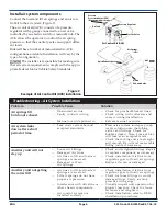
Install air system components

Connect the load and lift air springs and an air con-

trol kit to the air system (Figure 2). 
The air control kit (ACK) consists of a pressure 

regulator with a gauge connected to an air valve 

controlled by an electric switch or manual knob. The 

ACK allows the operator to control the air spring 

pressure so that the auxiliary axle can support differ

-

ent loads.  
Ridewell has a number of manual/electric ACK 

configurations available. Installation will vary by the 

type of configuration. 


The installer is responsible for making sure 

that air system requirements comply with the appro-

priate Federal Motor Vehicle Safety Standards. 

Air Tank

Air Control Kit (ACK)

Quick Exhaust Valve

Air Springs

(Load)

Quick 

Exhaust Valve

Air Springs

(Lift)

Pressure Regulator

Pressure 

Protection Valve (PPV)

(Required with air brakes)

Electric Valve 

Figure 2.

Example of Air Control Kit (ACK) installation

Summary of Contents for RSS-233

Page 1: ...g Installation 3 Prior to Installation Suspension Mounting Air Controls Troubleshooting Maintenance 7 Recommended Service Intervals Parts Illustration 20K Truck Suspension with Drum Brakes Drum Brake Axle Assembly 20K Truck Suspension with Disc Brakes Disc Brake Axle Assembly 20K Roll Off Suspension Roll Off Drum Brake Axle Assembly Bushing Replacement Kit Bushing Replacement Procedure Appendix 15...

Page 2: ... Part Number 233xxxx refers to the individual model of the suspension system The nine digit Serial Number 1xxxxxxxx refers to the date and order of manufacture of the suspension Please refer to both the part number and serial num ber when contacting Ridewell for customer service replacement parts and warranty information Notes and Cautions All work should be performed by a properly trained technic...

Page 3: ...ehicle Safety Standards FMVSS 121 for more information The installer must verify there is sufficient clear ance for proper functioning of the auxiliary suspension air springs brake chambers steer ing components axle including axle to driveline clearance and tires Prior to Installation Refer to the engineering drawing to confirm dimen sional requirements and the range of ride heights available Inst...

Page 4: ...er must be located on the frame within six inches of the leading or trailing edge of the hanger 3 Check that the location provides adequate clear ance for suspension components Make sure the top of the hangers and air spring mounting plates are parallel to the chassis frame to maintain the proper caster angle 4 Hangers and air spring mounting plates should be perpendicular to the chassis frame and...

Page 5: ...n the rear of the tires on the same axle When the front dis tance is less than the rear distance the wheels are in a toe in positive toe condition The correct setting for the RSS 233 suspension should be toe in between 1 32 and 3 32 Check Wheel Toe Setting 1 Deflate the air springs 2 Lift the axle enough for tires to rotate freely Sup port with jack stands to ensure axle is level Air springs press...

Page 6: ...not have proper air pressure Interference with driveline or other chassis components Air control system not installed correctly Check installation Air line from regulator goes to load air springs Check for loose fittings or worn damaged lines Verify air tank pressure with gauge Visually inspect unit operation for proper clearance Check for loose fasteners and retighten Check installation refer to ...

Page 7: ...d and tie rod ends for damage and wear Lubricate tie rod ends Check that the tie rod boot is in place and completely over the end of the tie rod Replace entire tie rod end if boot is damaged Annually 100 000 miles of use ___ Inspect pivot connections for worn pivot bushings and replace if necessary Torque pivot hardware and component bolts nuts to specifi cations Appendix ___ Check suspension hang...

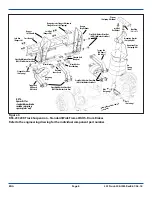
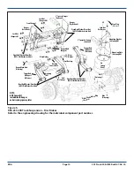
Page 8: ...her Pivot Nut HHCS FlatWasher LockNut Bolt AirSpring Air Spring Load Lock Nut Hanger RH Pivot Bushing WearWasher Mounting Plate AirSpring RH 2 Spacer AirSpring RHshown Hanger Locator Flange RHshown Flanged Screw Self Tapping Pivot Bolt Washer Pivot Nut HHCS FlatWasher LockNut Drum Brake Axle Assembly SteerLock Pivot Bolt Washer Pivot Nut HHCS FlatWasher LockNut Flanged Lock Nut AirSpring Bushing I...

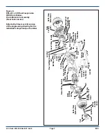
Page 9: ...te Gasket Spindle Nut Bearing Assembly Outer Bearing Bearing Assembly Seal Inner Bolt Steer Lock Brake Plunger Chamber Cap Gasket King Pin Shims Lock Nut Steer Lock Tube Assembly Hub Drum Options Avail Brake Assembly LH Draw Key Lock Nut Bolt Cotter Pin Lock Nut Tie Rod Arm Hub Drum Options Avail Steering Damper Bolt Bolt Flat Washer Gasket Cap Grease Fitting Knuckle LH Lock Nut Bolt Cotter Pin Lo...

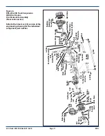
Page 10: ...asher Hanger Right Hand Mounting Bracket AirSpring RH Pivot Bolt Washer Pivot Nut HHCS FlatWasher LockNut Lock Nut Hanger RH Pivot Bushing Wear Washer Mounting Plate AirSpring RH 2 Spacer Air Spring Optional Pivot Bolt Washer Pivot Nut HHCS FlatWasher LockNut Disc Brake Axle Assembly SteerLock Pivot Bolt Washer Pivot Nut HHCS FlatWasher LockNut Flanged Lock Nuts AirSpring Bushing Inner Sleeve Flan...

Page 11: ... Pin Shims Lock Nut Steer Lock Tube Assembly Hub Rotor Bolt Draw Key Lock Nut Bolt Tie Rod Arm Cotter Pin Lock Nut Knuckle LH Hub Rotor Brake Cam Brake Caliper Torque Plate RH Bolt Tie Rod Arm Cotter Pin Steering Dampers Bolt Bolt Flat Washer Bolt Flat Washer Bolt Flat Washer Bearing Seal Thrust Bearing Cap Cap Gasket Lock Nut Lock Pin Woodruff Key Figure 6 RSS 233 20K Truck Suspension With Disc B...

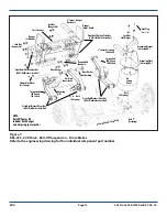
Page 12: ...nger LH WearWasher Hanger Right Hand Mounting Bracket AirSpring RH Pivot Bolt Washer Pivot Nut HHCS FlatWasher LockNut Lock Nut Hanger RH Pivot Bushing WearWasher Mounting Plate AirSpring RH 2 Spacer Air Spring Optional Pivot Bolt Washer Pivot Nut HHCS FlatWasher LockNut Drum Brake Axle Assembly Pivot Bolt Washer Pivot Nut HHCS FlatWasher LockNut Flanged Lock Nuts AirSpring Bushing Inner Sleeve Fl...

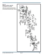
Page 13: ...le Nut Bearing Assembly Outer Bearing Bearing Assembly Seal Inner Bolt Cap Gasket King Pin Shims Hub Drum Brake Assembly LH Draw Key Lock Nut Bolt Cotter Pin Lock Nut Tie Rod Arm Hub Drum Bolt Flat Washer Gasket Cap Grease Fitting Knuckle LH L o c k N u t Bolt Cotter Pin Lock Nut Tie Rod Arm Grease Fitting Knuckle RH Bearing Seal Thrust Bearing Woodruff Key Flat Washer Bolt Lock Nut Lock Pin Brake...

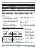
Page 14: ...excessive wear damage Replace if necessary NOTE Pivot hardware included with bushing re placement kit 3 Remove bushing assembly from torque rod and discard Clean the rod eye of any foreign debris corrosion 4 Apply Energy Suspensions Formula 5 Prelube to the bore inside of new bushings NOTE Do not Bushing Replacement Procedure Standard Wide Frame Width Figure 9 The number of wear washers on each si...

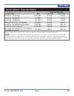
Page 15: ...Channel 5 8 11NC 160 ft lb 217 N m Pivot Bolt Hex Head Cap Screw HHCS Pivot Nut Lock Nut 7 8 14NF 500 ft lb 678 N m Torque values reflect a lubricated thread condition Nuts are pre lubed Do not overtorque Suspension is shipped with minimal torque applied to fasteners It is the installer s responsibility to apply the proper torque values All fasteners MUST be re torqued after the first 6 000 miles ...

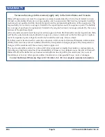
Page 16: ...ent Ride well has the sole discretion and authority to approve or deny a claim and authorize the repair or replace ment of suspension parts All parts must be held until the warranty claim is closed Parts that need to be returned for warranty evaluation will be issued a Returned Materials Authorization RMA Parts must be returned to Ridewell with the transportation charges prepaid The transportation...

Reviews: