Ricoh SP 310DN Service Manual Download Page 85

Electrical Components 


SM 

4-47 

M154/M155/M174/M175/A0A7/M287/M0BB


Rep

lacemen

an

d

 Ad

jus

tm

e

nt


Replacement Procedure 

M287/M289


1. Pull out the standard paper tray. 

2. Front cover (page 4-3 "Front Cover")   

3. Rear cover (page 4-7 "Rear Cover") 

4. Right cover (page 4-8 "Right Cover") 


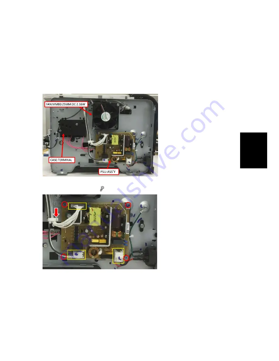
[Right side after taking the Right cover] 


5. Remove the PSU:ASS’Y. ( ×4, harness x3, clamp x1) 


Summary of Contents for SP 310DN

Page 1: ...M154 M155 M174 M175 A0A7 M287 M0BB SERVICE MANUAL...

Page 2: ...PERMISSION OF RICOH USA Inc All product names domain names or product illustrations including desktop images used in this document are trademarks registered trademarks or the property of their respect...

Page 3: ...Inc Users of this manual should be either service trained or certified by successfully completing a Ricoh Technical Training Program Untrained and uncertified users utilizing information contained in...

Page 4: ...EGEND PRODUCT CODE MODEL NAME M154 SP 311DN M155 SP 311DNw M174 SP 310DN M175 SP 311DNw M0A7 SP 320DN M287 SP 325DNw M0BB SP 377DNwX DOCUMENTATION HISTORY REV NO DATE COMMENTS 02 2017 Original Printin...

Page 5: ...INGS 2 1 Environment 2 1 2 1 2 MOVING AND TRANSPORTING THE MACHINE 2 2 3 PREVENTIVE MAINTENANCE 3 1 3 1 PREVENTIVE MAINTENANCE TABLES 3 1 3 2 IMAGE QUALITY STANDARDS 3 2 3 3 PAPER TRANSFER QUALITY STA...

Page 6: ...H 4 19 4 5 8 RELAY CLUTCH 4 20 4 5 9 REGISTRATION CLUTCH 4 20 4 5 10REGISTRATION ROLLER 4 21 4 5 11 REGISTRATION SENSOR 4 24 4 6 IMAGE TRANSFER 4 25 4 6 1 TRANSFER ROLLER 4 25 After installing a new t...

Page 7: ...EX 4 53 4 10 1RELAY SENSOR 4 53 4 10 2INVERTER SENSOR 4 53 5 SERVICE TABLES 5 1 5 1 SMART ORGANIZING MONITOR 5 1 5 1 1 OVERVIEW 5 1 5 1 2 PRINTER DRIVER INSTALLATION USB CONNECTION 5 1 5 1 3 ENTERING...

Page 8: ...1 SELF DIAGNOSTIC MODE AT POWER ON 6 1 6 2 SERVICE CALL 6 2 6 2 1 SUMMARY 6 2 Fusing related SCs 6 2 6 2 2 ENGINE SC 6 3 SC 2xx Laser Optics Error 6 3 SC 4xx Image Transfer and Transfer Error 6 5 SC 5...

Page 9: ...SAVE 7 1 7 1 ENERGY SAVE 7 1 7 1 1 ENERGY SAVER MODES 7 1 Timer Settings 7 1 Return to Stand by Mode 7 2 Recommendation 7 2 7 2 PAPER SAVE 7 3 7 2 1 EFFECTIVENESS OF DUPLEX COMBINE FUNCTION 7 3 1 Dupl...

Page 10: ......

Page 11: ...e extremely hot while the machine is operating Be careful to avoid touching those components with your bare hands Health Safety Conditions Toner is non toxic but if you get either of them in your eyes...

Page 12: ...r packages cartridges and bottles including used toner and empty bottles and cartridges out of the reach of children Always store fresh toner supplies or empty bottles or cartridges in a cool dry loca...

Page 13: ...t section Laser beams can seriously damage your eyes CAUTION MARKING Symbols Abbreviations and Trademarks This manual uses several symbols and abbreviations The meaning of those symbols and abbreviati...

Page 14: ...s Incorporated PCL is a registered trademark of Hewlett Packard Company Ethernet is a registered trademark of Xerox Corporation PowerPC is a registered trademark of International Business Machines Cor...

Page 15: ...PRODUCT INFORMATION REVISION HISTORY Page Date Added Updated New None...

Page 16: ......

Page 17: ...OVERVIEW 1 1 1 COMPONENT LAYOUT 1 Laser unit 9 Friction pad 2 Quenching lamp 10 Transfer roller 3 Cartridge AIO type 11 Paper Tray 4 Development roller 12 Fusing Unit 5 Registration roller 13 Pressure...

Page 18: ...view M154 M155 M174 M175 A0A7 M287 M0BB 1 2 SM 1 1 2 PAPER PATH A Duplex section B Standard paper tray unit 1 1 3 DRIVE LAYOUT 1 Duplex Motor 4 Relay Clutch 2 Main Motor 5 Paper Feed Clutch 3 Registra...

Page 19: ...RAME Item Machine Code Duplex Optional Tray PCL PS Wireless LAN Remarks SP 310DN M174 Auto N A Yes N A N A NEW SP 310DNw M175 Auto N A Yes N A Yes NEW SP 311DN M154 Auto N A Yes N A N A NEW SP 311DNw...

Page 20: ......

Page 21: ...INSTALLATION REVISION HISTORY Page Date Added Updated New None...

Page 22: ......

Page 23: ...is installed by the user Environment 1 Temperature Range 10 C to 32 C 50 F to 89 6 F 2 Humidity Range 15 to 80 RH 3 Ambient Illumination Less than 2 000 lux do not expose to direct sunlight 4 Ventilat...

Page 24: ...will break or cause injury if dropped When moving the printer after use do not take out any of the toners nor the waste toner bottle to prevent toner spill inside the printer Do not hold the control p...

Page 25: ...f The power cord is unplugged from the wall outlet The interface cable is unplugged from the printer 2 Lift the printer by using the inset grips on both sides of the printer and then move it horizonta...

Page 26: ......

Page 27: ...PREVENTIVE MAINTENANCE REVISION HISTORY Page Date Added Updated New None...

Page 28: ......

Page 29: ...Preventive Maintenance Tables SM 3 1 M154 M155 M174 M175 A0A7 M287 M0BB Preventive Maintenance 3 PREVENTIVE MAINTENANCE 3 1 PREVENTIVE MAINTENANCE TABLES There are no PM parts in this machine...

Page 30: ...Except Envelopes The standard print area of a sheet is the area enclosed by margins of 4 2 mm from all sides of the sheet Envelopes The 15mm excluding the flap portion from the rear end tip of the sh...

Page 31: ...ion Vertical Office All Environments 0 1 5mm Sub Scan Direction Scale Skew Single Side 1 0mm 100mm or less Less than B5 SEF 1 0mm 200mm or less B5 SEF or more tray 1 Bypass tray 1 0mm 50mm or less Byp...

Page 32: ...replaced in cases where their yield is near however given the APV Average Printer Volume for this product these yield parts 1 are expected to outlast the working life of the machine 1 Yield Parts Part...

Page 33: ...M0BB Preventive Maintenance 3 5 PREPARATION FOR PM 3 5 1 YIELD COUNTER Yield counters for each yield part can be checked by the following methods Configuration Page in the List Test Print menu Smart...

Page 34: ...plays Fuser life end notice Transfer roller life end notice or Life End of Paper Feed Roller Unit when one of these counters reaches its yield Counter Reset The process below shows how to reset the yi...

Page 35: ...ance 4 The Access Code entry dialog appears 5 Input the access code for customer engineers and then Click OK 6 Click the SP Mode 3 tab 7 Click Clear Transfer Roller EM Counter Clear Paper Feed Roller...

Page 36: ......

Page 37: ...REPLACEMENT AND ADJUSTMENT REVISION HISTORY Page Date Added Updated New None...

Page 38: ......

Page 39: ...Replacement and Adjustment 4 REPLACEMENT AND ADJUSTMENT 4 1 GENERAL CAUTIONS If there are printer jobs in the machine print out all jobs in the printer buffer Turn off the main power switch and unplu...

Page 40: ...l Tools M154 M155 M174 M175 A0A7 M287 M0BB 4 2 SM 4 2 SPECIAL TOOLS PC Windows XP Vista 7 8 Windows Server 2003 2003 R2 2008 2008 R2 2012 USB or network cable A computer is necessary to update the fir...

Page 41: ...A0A7 M287 M0BB Replacement and Adjustment 4 3 EXTERIOR COVERS 4 3 1 FRONT COVER 1 Pull out the standard paper tray A 2 Two tabs A 3 On the right side push down the tab and then slide the bypass tray A...

Page 42: ...74 M175 A0A7 M287 M0BB 4 4 SM 5 Open the front cover A To open the front cover push the cover release button B and carefully pull the cover forward and open it hinges downward 6 Push the right hinge A...

Page 43: ...r page 4 7 Rear Cover 3 Remove two screws A on the front side of the left cover 4 Remove a screw A on the rear upper side of the left cover 5 Pull the rear upper part A of the left cover to release th...

Page 44: ...dicating the position of the hooks 7 Pull the front bottom part of the left cover A to release the hooks The outside of the cover has marks indicating the position of the hooks 8 Left cover A There ar...

Page 45: ...rior Covers SM 4 7 M154 M155 M174 M175 A0A7 M287 M0BB Replacement and Adjustment 4 3 3 REAR COVER 1 Open the rear cover A 2 Slide the shaft B in the direction of the blue arrow and remove the rear cov...

Page 46: ...ont cover page 4 3 Front Cover 2 Rear cover page 4 7 Rear Cover 3 Right cover A x 3 hook at arrow mark The outside of the cover has marks indicating the position of the hooks There are many hooks and...

Page 47: ...Exterior Covers SM 4 9 M154 M155 M174 M175 A0A7 M287 M0BB Replacement and Adjustment...

Page 48: ...M175 A0A7 M287 M0BB 4 10 SM 4 3 5 TOP COVER 1 Front cover page 4 3 Front Cover 2 Rear cover page 4 7 Rear Cover 3 Left cover page 4 5 Left Cover 4 Right cover page 4 8 Right Cover 5 Top cover A x 4 x...

Page 49: ...g the top cover always verify that the two paperweights A are lifted If they are not lifted to fit into the paper slot the paperweights A could be damaged Make sure that these paperweights A can be mo...

Page 50: ...n seriously damage your eyes 4 4 1 CAUTION DECAL LOCATIONS A caution decal is attached as shown below Be sure to turn off the main switch and disconnect the power plug from the power outlet before beg...

Page 51: ...eplacement and Adjustment 4 4 2 LASER UNIT 1 Front cover page 4 3 Front Cover 2 Rear cover page 4 7 Rear Cover 3 Left cover page 4 5 Left Cover 4 Right cover page 4 8 Right Cover 5 Top cover page 4 10...

Page 52: ...f the main switch and unplug the machine before attempting any of the procedures in this section Laser beams can seriously damage your eyes 1 Top cover page 4 10 Top Cover 2 Polygon mirror cover A x 2...

Page 53: ...r 3 AIO 4 Set the machine with the rear side facing down resting on the table 5 Slide the paper feed shaft A to the left side x 2 6 Slide the paper feed roller B to the right side and remove it hook A...

Page 54: ...on pad do it in this order 1 Replace the spring 2 Insert the right side of the friction pad first followed by the left side 3 Gently push the friction pad down into the slot and then pull forward very...

Page 55: ...er 3 Right cover page 4 8 Right Cover 4 Pull out the paper tray 5 By pass lower guide plate A x 4 x 2 x 2 Reinstall the by pass lower guide plate A while pressing the spring B Be careful that the spri...

Page 56: ...by pass feed roller shaft A to the left side and remove it 10 Remove the metal cover B from the by pass feed roller C 4 5 5 BY PASS FEED ROLLER FRICTION PAD 1 By pass feed roller page 4 17 By pass Fe...

Page 57: ...B Replacement and Adjustment 4 5 6 BY PASS FEED SENSOR 1 Front cover page 4 3 Front Cover 2 Right cover page 4 8 Right Cover 3 By pass feed sensor A 3 hooks x 1 4 5 7 PAPER FEED CLUTCH 1 Drive unit pa...

Page 58: ...ed M154 M155 M174 M175 A0A7 M287 M0BB 4 20 SM 4 5 8 RELAY CLUTCH 1 Drive unit page 4 37 Drive Unit 2 Relay clutch A x 1 4 5 9 REGISTRATION CLUTCH 1 Drive unit page 4 37 Drive Unit 2 Registration clutc...

Page 59: ...Top Cover 4 Fusing Unit page 4 28 Fusing Unit 5 PSU HVP unit page 4 42 PSU 6 By pass lower guide plate page 4 17 By pass Feed Roller 7 Paper feed clutch page 4 19 Paper Feed Clutch 8 Relay clutch page...

Page 60: ...Paper Feed M154 M155 M174 M175 A0A7 M287 M0BB 4 22 SM 13 Imaging unit base A x 4 x 1 x 4 14 Registration unit A x 8 x 3...

Page 61: ...Paper Feed SM 4 23 M154 M155 M174 M175 A0A7 M287 M0BB Replacement and Adjustment 15 Upper guide plate A 2 hooks 16 Remove the registration roller follower A as shown below spring x 2 plastic parts x 2...

Page 62: ...4 M175 A0A7 M287 M0BB 4 24 SM 17 Registration roller drive A x 2 bushing x 2 4 5 11 REGISTRATION SENSOR 1 Registration unit page 4 21 Registration Roller 2 Turn the registration unit over 3 Registrati...

Page 63: ...transfer roller A as shown below 4 Remove the bushing x 2 spring x 2 gear x 1 collar x 1 from the transfer roller Do not touch the transfer roller surface when reinstalling the new transfer roller Af...

Page 64: ...Image Transfer M154 M155 M174 M175 A0A7 M287 M0BB 4 26 SM 4 6 2 TONER END SENSOR 1 Left cover page 4 5 Left Cover 2 Drive unit page 4 37 Drive Unit 3 Toner end sensor A 4 hooks...

Page 65: ...M175 A0A7 M287 M0BB Replacement and Adjustment 4 6 3 QUENCHING LAMP 1 Front cover page 4 3 Front Cover 2 Top cover page 4 10 Top Cover 3 AIO 4 Quenching lamp with the case A 2 hooks x 1 5 Remove the...

Page 66: ...ne from its power source and allow the fusing unit to cool before removing it 4 7 1 FUSING UNIT 1 Right cover page 4 8 Right Cover 2 Rear cover page 4 7 Rear Cover 3 Release the lock A and then remove...

Page 67: ...M174 M175 A0A7 M287 M0BB Replacement and Adjustment 6 Fusing unit A x 4 Make sure that the two bushings A remain in position Reinstallation Pass the cable A of the fusing unit through the hole B outs...

Page 68: ...r Configuration in SOM 2 Select the SP Mode 3 tab 3 Click Clear Fusing Unit EM Counter and then click OK 4 Exit the SOM 4 7 2 THERMOSTAT Do not recycle a thermoswitch that is already opened Safety is...

Page 69: ...and Exit SM 4 31 M154 M155 M174 M175 A0A7 M287 M0BB Replacement and Adjustment 4 7 3 THERMISTOR 1 Fusing unit page 4 28 Fusing Unit 2 Fusing upper cover A x 4 3 Fusing front cover A x 2 4 Thermistor...

Page 70: ...and Exit M154 M155 M174 M175 A0A7 M287 M0BB 4 32 SM 4 7 4 FUSING LAMP 1 Fusing unit page 4 28 Fusing Unit 2 Fusing side covers A x 2 each 3 Turn over the fusing unit 4 Ground wires x 1 each 5 Fusing...

Page 71: ...nt When reinstalling the fusing lamp The flat terminal A must be placed on the right side of the fusing unit fusing cable side 4 7 5 HOT ROLLER 1 Fusing lamp page 4 32 Fusing Lamp 2 Brackets A x 2 eac...

Page 72: ...4 M155 M174 M175 A0A7 M287 M0BB 4 34 SM 6 Fusing entrance guide A x 3 7 Thermistor page 4 31 Thermistor 8 Hot roller stripper pawls page 4 36 Hot Roller Stripper Pawls 9 Ground plate A x 2 each 10 Que...

Page 73: ...5 M174 M175 A0A7 M287 M0BB Replacement and Adjustment 11 Hot roller A 12 Remove the C ring x 2 gear x 1 cap x 1 bushing x 2 from the Hot Roller 4 7 6 PRESSURE ROLLER 1 Hot roller page 4 33 Hot Roller...

Page 74: ...PER PAWLS 1 Fusing unit page 4 28 Fusing Unit 2 Fusing upper cover page 4 30 Thermostat 3 Metal holders A 1 holder for each pawl x 2 each 4 Hot roller stripper pawls A 1 spring for each pawl 4 7 8 PAP...

Page 75: ...8 DRIVE 4 8 1 MAIN MOTOR 1 Left cover page 4 5 Left Cover 2 Harness guide plate A x 3 x 2 x 1 3 Main motor B x 4 x 1 4 8 2 DRIVE UNIT 1 Left cover page 4 5 Left Cover 2 Main board page 4 40 Main boar...

Page 76: ...Drive M154 M155 M174 M175 A0A7 M287 M0BB 4 38 SM 4 8 3 DUPLEX MOTOR 1 Left cover page 4 5 Left Cover 2 Duplex motor A x 2 x 1 x 1...

Page 77: ...75 A0A7 M287 M0BB Replacement and Adjustment 4 9 ELECTRICAL COMPONENTS When replacing a fuse always use a fuse of the correct rating Never use a fuse with the wrong rating If you do the machine may be...

Page 78: ...AIN BOARD 1 Left cover page 4 5 Left Cover 2 Main board A x 4 all s Do not connect any connectors to JRS1 and JRS2 when reinstalling the Main board A JRS1 and JRS2 are only used at the factory Do not...

Page 79: ...electricity Static electricity can damage EEPROM data Make sure that the EEPROM is correctly installed on the main board EEPROM Replacement procedures for the new EEPROM are included in the page 4 40...

Page 80: ...e bottom of the machine and the M287 M289 is behind the right side cover NEVER touch the areas outlined in red in the photos below to prevent electric shock caused by a residual charge A residual char...

Page 81: ...Cover 3 Rear cover page 4 7 Rear Cover 4 Left cover page 4 5 Left Cover 5 Right cover page 4 8 Right Cover 6 Top cover page 4 10 Top Cover 7 Main board page 4 40 Main board 8 Drive unit page 4 37 Driv...

Page 82: ...Electrical Components M154 M155 M174 M175 A0A7 M287 M0BB 4 44 SM 13 Rear lower cover A x 3 14 Release the lock A and then remove the entrance guide B x 1 15 Duplex cover A x 2 bushing x 2...

Page 83: ...5 M174 M175 A0A7 M287 M0BB Replacement and Adjustment 16 Set the machine with the front side facing down resting on the table 17 Release the link A x 1 18 Duplex transport guide A x 4 bushing x 4 x 1...

Page 84: ...Electrical Components M154 M155 M174 M175 A0A7 M287 M0BB 4 46 SM 20 PSU A x 4 x 1...

Page 85: ...ent and Adjustment Replacement Procedure M287 M289 1 Pull out the standard paper tray 2 Front cover page 4 3 Front Cover 3 Rear cover page 4 7 Rear Cover 4 Right cover page 4 8 Right Cover Right side...

Page 86: ...Electrical Components M154 M155 M174 M175 A0A7 M287 M0BB 4 48 SM 6 PSU ASS Y 4 9 4 HVP 1 PSU HVP unit page 4 42...

Page 87: ...Electrical Components SM 4 49 M154 M155 M174 M175 A0A7 M287 M0BB Replacement and Adjustment PSU 2 HVP A x 4 x 1...

Page 88: ...nts M154 M155 M174 M175 A0A7 M287 M0BB 4 50 SM 4 9 5 CHARGE TERMINAL CASE 1 Right cover page 4 8 Right Cover 2 Charge terminal case A with the harness x 2 x 1 2 hooks 3 Harness A x 4 4 Four springs an...

Page 89: ...M174 M175 A0A7 M287 M0BB Replacement and Adjustment 4 9 6 COOLING FAN 1 Right cover page 4 8 Right Cover 2 Top cover page 4 10 Top Cover 3 Cooling fan A x 2 x 1 x 2 Install the cooling fan A with its...

Page 90: ...mponents M154 M155 M174 M175 A0A7 M287 M0BB 4 52 SM 4 9 7 WIRELESS LAN BOARD FOR M155 M175 1 Left cover page 4 5 Left Cover 2 Top cover page 4 10 Top Cover 3 Remove the Wireless LAN board A from the t...

Page 91: ...75 A0A7 M287 M0BB Replacement and Adjustment 4 10 DUPLEX 4 10 1 RELAY SENSOR 1 Rear cover page 4 7 Rear Cover 2 Relay sensor A x 1 3 hooks 4 10 2 INVERTER SENSOR 1 Duplex transport guide page 4 42 PSU...

Page 92: ......

Page 93: ...SERVICE TABLES REVISION HISTORY Page Date Added Updated New None...

Page 94: ......

Page 95: ...ment appears 6 After reading the agreement click I accept the agreement and then click Next 7 In the Method to install printer driver dialog box clear the Search for network printers check box select...

Page 96: ...55 M174 M175 A0A7 M287 M0BB 5 2 SM 5 1 3 ENTERING THE PRINTER CONFIGURATION To enter the service system setting 1 Start the SOM utility 2 Click the User Tools tab 3 Click Printer Configuration 4 The A...

Page 97: ...Smart Organizing Monitor SM 5 3 M154 M155 M174 M175 A0A7 M287 M0BB Service Tables 5 Input the access code for customer engineers 6 Click the OK button 7 The Printer Configuration GUI appears...

Page 98: ...image registration and executes the color registration adjustment System Adjusts the system settings of the machine IPv6 Adjusts network settings IPv6 Network 1 Adjusts network settings Information In...

Page 99: ...hick Paper 1 Thick Paper 2 Plain Paper 1 Recycled Paper Color Paper Preprinted Paper Prepunched Paper Letterhead Bond Paper Cardstock Labels Default The selectable paper types depend on the model For...

Page 100: ...m value then it will be treated as the minimum value Custom Paper Size Bypass Horizontal 90 216mm Vertical 140 356mm 3 54 8 50 inch Precision is two digits after the decimal point in inch or one digit...

Page 101: ...reset to the factory defaults this value does not change Adjustment Vertical 15 to 15 step 0 1 mm per step Range is 15 mm to 15 mm If the machine settings are reset to the factory defaults this value...

Page 102: ...5 A0A7 M287 M0BB 5 8 SM Group Tab Item Selections Remarks Adjustment Horizontal 15 to 15 step 0 1 mm per step Range is 15 mm to 15 mm Adjustment Vertical 15 to 15 step 0 1mm per step Range is 15 mm to...

Page 103: ...Off Copies 1 999 Sub Paper Size Off Auto 2 Sided Print Off Short Edge Bind Long Edge Bind Blank Page Print Print Not Print Manual Duplex Cover has higher priority than the Blank Pages setting Energy...

Page 104: ...32 alphanumeric characters The factory default is null string Restore to Factory Default button Restores all settings to the factory default settings for the market area setting Language English The f...

Page 105: ...A0A7 M287 M0BB Service Tables Item Selections Remarks Russian Brazilian Turkish Access Code Use Do not use Access code change button Changes the access code The button is grey if the Access code is s...

Page 106: ...ess Displays Stateless Auto Address Link Local Address Displays Link Local Address IPv6 default router Gateway Displays IPv6 Default Gateway Manual Address Input IPv6 Address Manually Prefix length In...

Page 107: ...ting is changed the printer power must be turned off on for the new setting to take effect The default setting is 192 0 0 192 when DHCP is off Subnet Mask xxx xxx xxx xxx This setting is not available...

Page 108: ...the end of network initialization The default setting is 192 0 0 192 when DHCP is off TCP IP DHCP On Off If this setting is changed the printer power must be turned off on for the new setting to take...

Page 109: ...DHCP is off is null string The setting when DHCP is changed from on to off is the previous setting when DHCP was on If this setting is changed the printer power must be turned off on for the new setti...

Page 110: ...string Port Number 25 1 to 65535 The factory default is 25 User Name Null string Up to 32 alphanumeric characters The factory default is null string Password Null string Up to 32 alphanumeric characte...

Page 111: ...Community public Up to 15 alphanumeric characters Manager IP Address 0 0 0 0 The factory default is 0 0 0 0 If this setting is changed the printer power must be turned off on for the new setting to ta...

Page 112: ...ers Print Cartridge Empty Service Required E mail Address Print Cartridge Near Empty Up to 64 alphanumeric characters No Paper Cover Open Alert 2 Display Name Paper Jam Up to 32 alphanumeric character...

Page 113: ...Wireless LAN Status MAC Address Communication Mode SSID Channel Indication of Wireless Signal Strength Configuration Method Manual Setup Setup with WPS Wireless LAN Setting SSID Input SSID Communicat...

Page 114: ...Mode WPA WPA2 Encryption None Selects encryption method WEP WPA Passphrase Input WPA passphrase WEP Key Length 64bit 128bit Selects WEP key length WEP Transmit Key ID 1 to 4 WEP Key Format Hexadecima...

Page 115: ...PCL Orientation Portrait Landscape Form Lines 5 to 128 by 1 If the machine settings are reset to the factory defaults this value does not change Font Number 0 89 The factory default value is 0 Font Si...

Page 116: ...PC 8 PC 8 D N PC 850 PC 852 PC 858 PC 8 TK Win L1 Win L2 Win L5 Desktop PS Text VN Intl VN US MS Publ Math 8 PS Math VN Math Pi Font Legal ISO 4 ISO 6 ISO 11 ISO 15 ISO 17 ISO 21 ISO 60 ISO 69 Win 3...

Page 117: ...not change 40 to 40 0 Default 0 1 mm step Vertical Thick Paper Adjusts the vertical registration of thick paper for tray 1 If the machine settings are reset to the factory defaults this value does not...

Page 118: ...m step Registration Duplex Tray Horizontal Adjusts the horizontal registration the back side in duplex mode If the machine settings are reset to the factory defaults this value does not change 40 to 4...

Page 119: ...h Output check Registration Clutch Reverse Clutch Output check Reverse Clutch Fan High Speed Output check Fan High Speed Fan Low Speed Output check Fan Low Speed Erase Lamp Output check Quenching Lamp...

Page 120: ...ault 1 mm step Amount of Paper Buckle at the Registration Roller Bypass Tray Vertical Plain Paper Adjusts the amount of paper buckle at the registration roller for each tray and paper type 8 to 8 2 De...

Page 121: ...postcard 160 to 200 185 Default 5 C step Thick Paper 2 Adjusts the fusing temperature for thick 2 paper 160 to 200 185 Default 5 C step Recycled Adjusts the fusing temperature for recycled paper 150 t...

Page 122: ...3 Destination Sets the destination and updates the engine setting Do not change this setting Designed for Factory Use JPN NA EU ASIA China TAIWAN PnP ID Do not change this setting Designed for Factor...

Page 123: ...eets between toner near end to toner end 0 to 255 200 1 sheet step Printable Dot Count Adjusts the printable dot count between toner near end to toner end 0 to 255 100 1 dot step PDL Menu ON PDL Setti...

Page 124: ...isplay Sets the display of alert when each EM parts yield of this machine is reached On Default or Off Clear Engine Memory Resets the engine settings stored in the EEPROM to factory default Reset Fusi...

Page 125: ...ation about the machine s status Print this sheet as shown below Check the configuration page when doing machine maintenance To Print the Configuration Page 1 Start the SOM utility 2 Click the User To...

Page 126: ...engine The value is calculated as follows Total counter Printer counter Reports print Application Counters Application counters exist for each individual primary machine function and are incremented b...

Page 127: ...ent configuration and installed PCL font list Maintenance Page Web image monitor only Prints the maintenance status 5 2 3 TEST PAGE When you check an image problem or other problems it might be necess...

Page 128: ...A0A7 M287 M0BB 5 34 SM 5 2 4 TEST PATTERN PRINTING Follow the test pattern print procedure below to print a test pattern To Print the Test Pattern 1 Start the SOM utility 2 Click the User Tools tab 3...

Page 129: ...e Access Code entry dialog appears 5 Input the access code for customer engineers and then Click OK 6 Select the SP Mode 2 tab 7 Click Print Test Pattern 8 The following three test pattern pages Check...

Page 130: ...ul Follow the procedure carefully and note that it will vary in parts depending on which version of the firmware is currently installed Procedure When updating firmware always disconnect any other cab...

Page 131: ...o check the machine s firmware version 5 3 3 UPDATING THE BOOT LOADER FIRMWARE This is also listed on the configuration page but this firmware is not updated in the field 5 3 4 UPDATING FAILURE If the...

Page 132: ...hether the printer is available F W file transmission cannot be completed Transmission will be canceled if timeout Check USB cable connection Check whether the USB Print Driver is available Check whet...

Page 133: ...able Check the printer and PC IP address setting Check the PC firewall setting about FTP F W file transmission can not be completed Transmission will be canceled if timeout 1 Check network cable conne...

Page 134: ...pdate is running Other Printer functions are running Please wait until F W update is completed Please wait until other printer functions are completed FW Update Done Please reboot the Machine F W upda...

Page 135: ...te is running Other Printer functions are running Please wait until F W update is completed Please wait until other printer functions are completed FW Update Done Please reboot the Machine F W update...

Page 136: ......

Page 137: ...TROUBLESHOOTING REVISION HISTORY Page Date Added Updated New None...

Page 138: ......

Page 139: ...on the controller waits for the initial settings of the copy engine to take effect and then starts an independent self diagnostic test program The self diagnostic test checks the CPU memory and so on...

Page 140: ...off and on if an SC code is displayed 3 First disconnect then reconnect the connectors before replacing the PCBs if the problem concerns electrical circuit boards 4 First check the mechanical load be...

Page 141: ...mirror motor does not leave the READY status within 20 sec after the polygon mirror motor switched off Polygon motor driver board harness loose or disconnected Polygon motor driver board defective Las...

Page 142: ...Turn the machine main power off on 2 Check the connectors 3 Replace the laser optics unit 4 Replace the Main board 268 Laser Scanning Unit thermistor error At power on the temperature sensor in the op...

Page 143: ...nt charge or transfer charge PWM signals are sampled at 20 msec intervals This SC is issued if 10 PWM samplings within 200 msec are abnormal HVPS harness loose broken defective HVPS board defective AI...

Page 144: ...machine s main power off and then on 2 Check or replace the main motor if the torque load is normal 3 Replace the motor harness 530 Exhaust fun Error The FAN lock signal High for 10 seconds after the...

Page 145: ...mperature did not reach 45 degrees C within 11 seconds after the fusing lamp turned ON 3 The fusing temperature did not reach the reload temperature within 35 seconds in a normal high temperature oper...

Page 146: ...mistor not in the correct position Defective fusing lamp 1 Replace the fusing unit 2 Replace the fusing lamp Execute Reset Fusing Unit SC to recover the machine after completing the recovery procedure...

Page 147: ...t 4 The fusing temperature was 100 degrees C or more below the target temperature for 5 2 seconds during the waiting and printing statuses In a 200V power supply environment 1 The fusing temperature i...

Page 148: ...removal Execute Reset Fusing Unit SC to recover the machine after completing the recovery procedure Otherwise the machine continues to issue this SC code and cannot be operated SC 6xx Communication an...

Page 149: ...ENSOR LAYOUT There are the sensors of the jam detection as shown below Paper Jam 1 Registration Sensor 2 Inverter Sensor 3 Paper Exit Sensor 4 Relay Sensor 6 3 2 JAM MESSAGE LIST Here is a list of com...

Page 150: ...ation sensor duplex feed tray Registration sensor 1 Paper does not reach duplex entry sensor Relay sensor 5 Paper does not reach duplex exit sensor Inverter sensor 3 Internal Misfeed Paper stayed on r...

Page 151: ...with the SOM Printer Configuration For details see the Software Guide Service Adjustment 1 Print the test page page 5 31 Reports Print out the test page before changing the paper registration setting...

Page 152: ...ect the SP Mode 1 tab 8 Click Up or Down to set the registration value mm and then click OK Increase the value to shift the print area in the plus direction Decrease to shift in the minus direction Ad...

Page 153: ...Image Adjustment SM 6 15 M154 M155 M174 M175 A0A7 M287 M0BB Troubleshooting 1 Feed Direction 2 Vertical Adjustment 3 Horizontal Adjustment 4 Print Area 9 Exit the SOM...

Page 154: ...ntervals Abnormal image at 29 8 mm intervals Charge roller Abnormal image at 37 7 mm intervals Registration roller Colored spots at 37 9 mm intervals Print cartridge Development roller Abnormal image...

Page 155: ...ervals This is because low humidity conditions tend to cause variations in light sensitivity across the surface of the drum Selecting On for Low Humidity Mode under the System tab in Printer Configura...

Page 156: ...e tray Paper jams occur frequently There remain pieces of paper in the paper path Poor contact or disconnection of the sensor There is some foreign body in the paper guides of the paper path If there...

Page 157: ...one left in the tray Paper gets wrinkles Deterioration of the hot roller or the pressure roller Paper is damp Use paper that has been stored properly Paper is too thin If there are gaps between the pa...

Page 158: ...ot dry Do not touch printed surfaces immediately after copying Remove freshly printed sheets one by one taking care not to touch printed areas Dirty background Replace the print cartridge Adjust with...

Page 159: ...ENERGY SAVE REVISION HISTORY Page Date Added Updated New None...

Page 160: ......

Page 161: ...aded grey in this diagram represents the amount of energy that is saved when the timers are at the default settings If the timers are changed then the energy saved will be different For example if the...

Page 162: ...consider the effects on the environment of extra energy use If it is necessary to change the settings please try to make sure that the Energy Saver Mode 2 Timer is not too long Try with a shorter set...

Page 163: ...EFFECTIVENESS OF DUPLEX COMBINE FUNCTION Duplexing and the combine functions reduce the amount of paper used This means that less energy overall is used for paper production which improves the enviro...

Page 164: ...pages that have images on both sides For one duplex page the duplex counter goes up by 1 For a duplex job of a three page original the duplex counter will only increase by 1 even though two sheets are...

Page 165: ...10 5 5 10 20 20 10 10 20 If combine mode is used the total and duplex counters work in the same way as explained previously The following table shows paper savings and how the counters increase for so...

Page 166: ...M287 M0BB 7 6 SM Duplex 2 in 1 mode Originals Simplex Sheet used Duplex Sheets used Paper Saved Total counter 1 1 1 0 1 2 2 1 1 1 3 3 1 2 2 4 4 1 3 2 5 5 2 3 3 6 6 2 4 3 7 7 2 5 4 8 8 2 6 4 9 9 3 6 5...

Page 167: ...M154 M155 M174 M175 A0A7 M287 M0BB SERVICE MANUAL APPENDICES...

Page 168: ......

Page 169: ...ICES SPECIFICATIONS 1 1 1 1 GENERAL SPECIFICATIONS 1 1 1 1 1 GENERAL SPECIFICATIONS 1 1 1 1 2 PRINTER 1 3 1 2 SUPPORTED PAPER SIZES 1 4 2 ERROR MESSAGES 2 1 2 1 1 OVERVIEW 2 1 2 1 2 ERROR MESSAGES LIS...

Page 170: ......

Page 171: ...APPENDIX SPECIFICATIONS REVISION HISTORY Page Date Added Updated New None...

Page 172: ......

Page 173: ...m 8 5 x 14 By pass tray A4 B5 A5 B6 A6 Legal Letter HLT Exective F Foolscap Folio 16K Custom size Min 90 x 148 mm 3 9 x 5 8 Max 216 x 356 mm 8 5 x 14 Duplex A4 Legal Letter 8 1 2 x11 Paper weight Main...

Page 174: ...Saver Mode 2 Power US 120V 7A 60Hz EU AP 220 240 V 4A 50 60Hz CH 220 240 V 5A 50 60Hz Noise Printing Less than 65 8 dB A Standby Mode 40 dB A Energy Saver 40 dB A Warm up time 26 seconds or less 23 C...

Page 175: ...nt 80 fonts Resolution 600 x 600 dpi Maximum 1200 x 600 dpi Toner save mode Supported First print speed 12 seconds or less Duplex print Supported PC interface Ethernet 10BASE T 100BASE TX USB 2 0 Wi F...

Page 176: ...pe Standard Tray Duplex Plain Paper A4 SEF 210x297mm A B Y LEF 297x210mm N N N B5 SEF 182x257mm A B N LEF 257x182mm N N N A5 SEF 148x210mm A B N LEF 210x148mm N C N B6 SEF 128x182mm B B N LEF 182x128m...

Page 177: ...8 x 9 1 2 N B Env Monarch Env Monarch SEF 3 7 8 x 7 1 2 N B Env C6 Env C6 SEF 114 x 162mm N B Env C5 Env C5 SEF 162 x 229mm N B Env DL Env DL SEF 110 x 220mm N B Custom Width Width 100 216mm 3 6 x 8 5...

Page 178: ......

Page 179: ...SM Appendix 1 1 M154 M155 M174 M175 A0A7 M287 M0BB ERROR MESSAGES REVISION HISTORY Page Date Added Updated New None...

Page 180: ......

Page 181: ...ed paper source tray is not set properly or no paper loaded Check the indicated tray Tray 1 has run out of paper The bypass tray has run out of paper Load paper into Tray 1 See the user s guide Loadin...

Page 182: ...printing becomes not available Please keep Print Cartridge handy The machine has run out of the toner Replace the print cartridge See the user s guide Replacing the Print Cartridge Printing has been i...

Page 183: ...the print cartridge Set the print cartridge again correctly Load paper into the tray Flashing On A paper jam has occurred in the machine Use Web Image Monitor or Smart Organizing Monitor to determine...

Page 184: ...BB 2 4 SM Appendix to check the error and then take appropriate measures See the user s guide Using Web Image Monitor or Using Smart Organizing Monitor On On On A malfunction has occurred Contact your...

Reviews: