background image

Front Panel

Rear panel


Front Panel

1.  

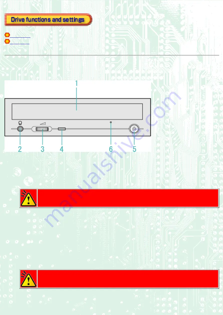
Disc tray

This is the tray for the disc. Place the disc on the ejected disc tray, then lightly push the tray (or push the eject 
button) and the disc will be mounted.

Caution

Don't use force to pull out or push in the disc tray. This might cause damage to the loading section of 
the drive.

2.  

Headphone jack

This jack is for connecting headphones or mini-speakers.

3.  

Volume control

This is used to adjust the output volume of the headphone jack. It can't be used to adjust the output volume for 
the audio output connectors on the rear panel.

Caution

Turn the volume down before turning on the power. Sudden loud noises can damage your hearing.

4.  

Busy indicator

Summary of Contents for MP5163A

Page 1: ...on the user is encouraged to try to correct the interference by one or more of the following measures Reorient or relocate the receiving antenna Increase the separation between the equipment and rece...

Page 2: ...icht Declaration of Conformity The Product complies with the requirements of the EMC Directive 89 366 EEC and the Low Voltage Directive 73 23 EEC Please take notice that the manufacturer of this equip...

Page 3: ...Microsoft Corporation Acrobat reader is trademark of Adobe Inc The company names and product names written in this manual are trademarks or registered trademarks...

Page 4: ...lating to the drive Failing to comply with the information in this manual and or incorrect handling of the drive may result in serious personal injury or damage to the product Indicates restriction or...

Page 5: ...drive allows you to play DVD ROM discs write to play and edit DVD RW discs play CD ROM discs write to and play CD R discs write to play and edit CD RW discs In order to operate the drive connected wi...

Page 6: ...d on our own is a new technology that predicts possible occurrences of buffer underrun errors in advance and automatically avoids them The MP5163A is the industry s first ever drive that features Just...

Page 7: ...rive or moisten a cloth with neutral detergent diluted with water and use it to clean particularly dirty areas Don t cutoff the electric power while the drive is operating When connecting two E IDE de...

Page 8: ...fig1 1 Check 2 Recording surface fig2 1 50 to 100mm Back...

Page 9: ...ink which we at Ricoh developed on our own is a new technology that predicts possible occurrences of buffer underrun errors in advance and automatically avoids them An improved anti heat design means...

Page 10: ...ve a free 5V 12V power terminal Recommended discs 2 Recommended Tested to be compatible CD R Ricoh Taiyo Yuden Mitsui Chemicals Mitsubishi Chemical Maxell CD RW Ricoh Mitsubishi Chemical 1 High Speed...

Page 11: ...in the disc tray This might cause damage to the loading section of the drive 2 Headphone jack This jack is for connecting headphones or mini speakers 3 Volume control This is used to adjust the output...

Page 12: ...ve has a function that allows the disc to be ejected manually if this becomes necessary in an emergency such as failure of the drive or a power outage Caution This feature is a last measure to be used...

Page 13: ...while the power is on as this could cause a short circuit and damage the system Always turn the power OFF when connecting or disconnecting the cable 5 Power Connector Connects to the power supply 5 an...

Page 14: ...cy eject hole The front door pops open and the disk tray comes partway out 3 Pull the front door to open it all the way then grip the disc tray between thumb and forefinger and gently pull it straight...

Page 15: ...he four vanes may be oriented just at the angles as shown below In such a case push the tip of the thin wire in the following direction with the wire angled at about 15 degrees so that the tray can ea...

Page 16: ...Disc ejection 1 Press the eject button 2 Slowly take the disc out of the disc tray 3 Press the eject button or push the disc tray and the tray will be inserted back into the drive...

Page 17: ...nside the unit quickly When the disc tray is in the ejected position dust and other debris will enter possibly causing read errors write errors or drive failure Back Next Load the disc Disc ejection E...

Page 18: ...an 80mm CD place it in the small round depression with its label side facing up Writing to an 80mm CD is not supported Only reading is possible The face with the label on it should be up Never place...

Page 19: ...3 Load the disc by pressing the eject button or by lightly pushing in the disc tray...

Page 20: ...Next Load the disc Disc ejection Emergency Eject Using the Drive in a Vertical Position...

Page 21: ...l position 1 Locate the four tabs on the disc tray 2 When loading a disc insert it into the inner side of the tabs Caution Cannot be used with 80mm CDs Cannot be used with business card CDs Back Load...

Page 22: ...screws for the drive unit The manual for the computer to know the location of the IDE connector Turn off all peripheral appliances of the computer and the computer itself and disconnect their power c...

Page 23: ...ique way A hard disk is normally installed as the Primary Master on the E IDE ATAPI interface Other E IDE peripheral devices such as hard drives and CD ROMs are then set accordingly Caution If two per...

Page 24: ...re than one jumper is installed the drive may malfunction or be damaged Next 1 Jumper Set Up 2 Removing the Computer Cover 3 Mounting the Drive 4 Connecting the Power Connector 5 PC Connections 6 Soun...

Page 25: ...r to the manual for the computer for details about removing the cover Caution There may be sharp edges inside the computer take care to avoid injury Back Next 1 Jumper Set Up 2 Removing the Computer C...

Page 26: ...e manual for the computer for details 2 Insert the drive unit into the bay Do not apply excessive pressure to the cables inside the computer 3 Secure the drive with the screws provided If there is not...

Page 27: ...Back Next 1 Jumper Set Up 2 Removing the Computer Cover 3 Mounting the Drive 4 Connecting the Power Connector 5 PC Connections 6 Sound Card Connection 7 Replacing the Computer Cover 8 Device Drivers...

Page 28: ...properly into the socket If there is no spare power cable available in the computer you will have to purchase a splitter cable of a suitable type Back Next 1 Jumper Set Up 2 Removing the Computer Cove...

Page 29: ...s follows 1 Master 2 Slave 3 Motherboard 4 Primary 5 Secondary 6 less than 6 inches 7 less than 18 inches To Install as a Master Drive To Install as a Slave Drive To Install as a Master Drive To insta...

Page 30: ...lave Drive To install the drive as a Slave change the jumper setting on the rear panel 1 Master drive Booting hard disk 2 Slave drive the drive 3 Secondary connector 4 Primary connector 5 Master drive...

Page 31: ...Back Next 1 Jumper Set Up 2 Removing the Computer Cover 3 Mounting the Drive 4 Connecting the Power Connector 5 PC Connections 6 Sound Card Connection 7 Replacing the Computer Cover 8 Device Drivers...

Page 32: ...onds to L and R to R Refer to the manual for the sound card for detailed information regarding connection 1 The drive 2 When L R 3 Sound Card 4 Motherboard 5 Primary or Secondary Back Next 1 Jumper Se...

Page 33: ...f the drive unit is complete replace the computer cover Back Next 1 Jumper Set Up 2 Removing the Computer Cover 3 Mounting the Drive 4 Connecting the Power Connector 5 PC Connections 6 Sound Card Conn...

Page 34: ...4 0 Users The drive is displayed on the IDE controller in control panels SCSI adapter devices For Windows 2000 Professional Users The drive is displayed in control panels system hardware device manag...

Page 35: ...eed to contact your PC manufacturer or the motherboard manufacturer and get the appropriate E IDE controller driver Back 1 Jumper Set Up 2 Removing the Computer Cover 3 Mounting the Drive 4 Connecting...

Page 36: ...attach any stickers or labels to the discs Using discs with labels attached not only causes read and write errors but data on the disc may be lost due to damage to the disc itself Load the disc Disc...

Page 37: ...ata buffer memory 2MB Data transfer speed 33 3MB sec Max UDMA33 CD R CD RW High Speed CD RW Write Read speed Ave Read Speed 40X 4 8MB sec 1 Write Speed CD R 4X 600KB sec 8X 1200KB sec 16X 2 4MB sec CD...

Page 38: ...cessing time CD ROM 14sec or less CD R RW also High Speed CD RW 19sec or less Mounting direction horizontal vertical eject button upper Writing Mode Track At Once Disc At Once Multi session Packet Wri...

Page 39: ...Reliability Error Rate 10 12 bits or less MTBF 100 000hours or greater MTTR Within 30 minutes Environmental Conditions When operating When not operating Temperature 5 C to 35 C No air cooling 30 C to...

Page 40: ...ic foot or less 1Speed is automatically reduced if reading is unsuccessful 2 Play means playback Also Read means transferring data 3CD i and Photo CD discs require special reader player Also Photo CD...

Page 41: ...All references to the product in this document are to specifications in effect when the product was released Copyright RICOH Co Ltd All rights reserved...

Reviews: