background image

Page I-21 

Revised: 9/1/2021 

Last Edited by: FR 

APX 1000+ Assembly Manual 


Item Code 

Qty for 

APX1000 

Qty for 

APX2000 

Qty for 

APX3000 

Qty for 

APX3000UW 

Description 

Image 

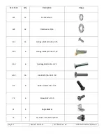
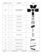
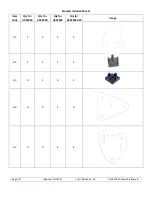
H1-3 

19 

25 

25 

25 

Hex Bolt ¼-20 x 2.25 


H2-1 

12 

10 

Hex Bolt 5/16-18 x 0.625 


H2-2 

Hex Bolt 5/16-18 x 1.75 


P1 

Screw 6-32 x 0.75 


F1 

Flat Head Bolt ¼-20 x 

1.50 


Summary of Contents for AP-Xtreme

Page 1: ...tions available for the AP Xtreme chassis Some sections of this guide will be skipped based on the options chosen APX1000 APX2000 APX3000 APX3000UW SlipSense gSense VR Option Pedal Options Floor Mount Hanging Mount Dead Pedal 4th Monitor Mount Shaker Option Shifter Mount Option Speakers Button Box Hand Brake Pro Shifter Pro Seat Rails WindSense ...

Page 2: ...Page I 2 Revised 9 1 2021 Last Edited by FR APX 1000 Assembly Manual ...

Page 3: ...e times are for assembly of the chassis and mounting the peripherals only Connecting components configuring your system and cable management will require additional time APX 1000 about 4 hours APX 2000 about 5 hours APX 3000 about 6 hours APX 3000UW about 7 hours Slip Sense Add On about 3 additional hours Pay particular attention to comments marked with the symbol Please call us if you have any pr...

Page 4: ...I 4 Revised 9 1 2021 Last Edited by FR APX 1000 Assembly Manual these projects are usually undertaken outside of normal business hours and we will try to help you as best we can during that time 305 417 9241 ...

Page 5: ...Page I 5 Revised 9 1 2021 Last Edited by FR APX 1000 Assembly Manual Section A AP Xtreme Slip Sense Assembly Contents Panels Included Item Code Qty Image T1 2 T2 2 T3 1 T4 1 T5 1 ...

Page 6: ...ed by FR APX 1000 Assembly Manual Item Code Qty Image T6 1 T7 1 Extrusion Profile Item Code Qty Size Image ET1 2 3 x 1 5 x 66 ET2 2 1 5 x 1 5 x 30 5 Hardware Included Item Code Qty Description Image N1 6 Hex Nut 20 N2 24 Hex Nut 5 16 18 ...

Page 7: ...tion Image W1 12 Flat Washer W2 32 Flat Washer 5 16 C2 1 14 Carriage Bolt 5 16 18 x 0 75 C2 2 6 Carriage Bolt 5 16 18 x 1 25 C1 3 6 Carriage Bolt 20 x 3 25 H2 2 16 Hex Bolt 5 16 18 x 1 50 B2 8 Button Head 5 16 x 1 25 P2 6 Screw 8 32 x 0 50 L1 4 Angle Bracket L2 4 5 16 18 T Slot Nut and Bolt ...

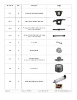
Page 8: ...d Assembly R1 R 2 Rear Roller and Guard Assembly N4 A 4 Threaded Insert Plate with 1 set screw may be pre installed N4 B 2 Threaded Insert Plate with 2 set screws may be pre installed R3 2 Guide Bolt R4 1 Bronze Bearing A10 4 Vibration Mount 4 more included with main chassis PF1 4 Rubber Feet SX1 1 Slip Sense Actuator w Coupling ...

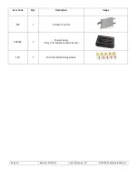
Page 9: ...I 9 Revised 9 1 2021 Last Edited by FR APX 1000 Assembly Manual Item Code Qty Description Image SX2 1 Actuator Control SX4000 1 Power Supply Only 1 for SlipSense and G Sense FGK 1 Pinch Hazard Warning Decals ...

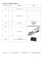
Page 10: ...FR APX 1000 Assembly Manual Section 2 G Sense Components Item Code Qty Description Image GB1 1 G Sense Actuator Top GB2 1 Actuator Cover Panel GA1 2 Flat Washer GA2 1 SXG 2 G Sense Actuator SX4000 1 Power Supply Only 1 for SlipSense and G Sense ...

Page 11: ...ion Image GBELT 1 Specially Modified Belts for G Sense System S4 2 Spacer Sleeve N1 3 Hex Nut 20 N2 2 Hex Nut 5 16 18 N3 2 Dowel Nut 20 W1 5 Flat Washer W2 4 Flat Washer 5 16 C2 4 2 Carriage Bolt 5 16 18 x 1 25 H1 3 2 Hex Bolt 20 x 2 25 H1 4 3 Carriage Bolt 20 x 3 25 HG1 8 Allen Head 10 x 1 00 ...

Page 12: ...Page I 12 Revised 9 1 2021 Last Edited by FR APX 1000 Assembly Manual Item Code Qty Description Image NG1 8 10 Flanged Nut ...

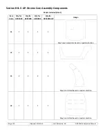
Page 13: ...re Assembly Components Panels Included Box 1 Item Code Qty for APX1000 Qty for APX2000 Qty for APX3000 Qty for APX3000UW Image B1 1 1 1 1 May have holes slots based on pedal selection B2 1 1 1 1 B3 2 2 2 2 May be omitted based on pedal selection B4 1 1 1 1 May be omitted based on pedal selection ...

Page 14: ...l Item Code Qty for APX1000 Qty for APX2000 Qty for APX3000 Qty for APX3000UW Image B5 2 2 2 2 B6 1 1 1 1 May have additional holes based on wheel selection B7 2 2 2 2 B8 1 1 1 1 May be omitted based on pedal selection B9 1 1 1 1 May be omitted based on pedal selection ...

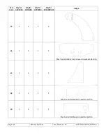
Page 15: ...Assembly Manual Item Code Qty for APX1000 Qty for APX2000 Qty for APX3000 Qty for APX3000UW Image B10 1 1 1 1 B11 0 2 2 2 B12 0 1 1 1 B13 4 2 Tall 2 Short 4 2 Tall 2 Short 4 2 Tall 2 Short 4 2 Tall 2 Short May be omitted based on seat selection B15 4 4 4 4 ...

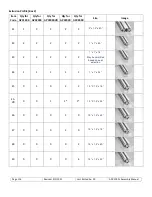
Page 16: ...R Qty for APX3000 Qty for APX3000 Size Image E1 2 2 2 2 2 3 x 1 5 x 60 E2 2 2 2 2 2 1 x 1 x 60 E3 2 2 2 2 2 1 x 1 x 18 May be ommitted based on seat selection E4 1 1 1 1 1 1 x 1 x 24 E5 0 1 0 2 2 1 5 X 1 5 x 16 E5 VR 0 0 1 1 1 1 5 X 1 5 x 24 E6 0 0 0 1 0 1 5 x 1 5 x 42 E7 0 0 0 2 0 1 5 x 1 5 x 18 E8 0 0 0 0 2 1 5 x 1 5 x 60 E9 0 0 0 0 4 1 5 x 1 5 x 22 ...

Page 17: ...sed 9 1 2021 Last Edited by FR APX 1000 Assembly Manual Brackets Included Box 3 Item Code Qty for APX1000 Qty for APX2000 Qty for APX3000 Qty for APX3000UW Image A1 2 2 2 2 A4 1 1 1 1 A5 0 1 6 2 A6 0 0 2 0 A7 0 0 4 4 ...

Page 18: ...Page I 18 Revised 9 1 2021 Last Edited by FR APX 1000 Assembly Manual Item Code Qty for APX1000 Qty for APX2000 Qty for APX3000 Qty for APX3000UW Image A8 0 0 3 0 A9 0 1 3 3 A10 4 4 4 4 A11 0 0 0 2 ...

Page 19: ...Page I 19 Revised 9 1 2021 Last Edited by FR APX 1000 Assembly Manual Item Code Qty for APX1000 Qty for APX2000 Qty for APX3000 Qty for APX3000UW Image A12 0 0 0 4 A13 0 0 0 2 A14 1 1 1 1 ...

Page 20: ...Image N1 18 24 24 24 Hex Nut 20 N2 36 40 70 78 Hex Nut 5 16 18 N3 19 25 25 25 Dowel Nut 20 W1 57 69 69 69 Flat Washer W2 44 49 90 96 Flat Washer 5 16 C1 1 4 4 4 4 Carriage Bolt 20 x 0 50 C1 2 12 18 18 18 Carriage Bolt 20 x 1 25 C2 1 12 14 42 50 Carriage Bolt 5 16 18 x 0 625 C2 2 24 26 28 28 Carriage Bolt 5 16 18 x 1 25 H1 1 5 5 5 5 Hex Bolt 20 x 0 75 H1 2 5 5 5 5 Hex Bolt 20 x 1 75 ...

Page 21: ...Item Code Qty for APX1000 Qty for APX2000 Qty for APX3000 Qty for APX3000UW Description Image H1 3 19 25 25 25 Hex Bolt 20 x 2 25 H2 1 0 1 12 10 Hex Bolt 5 16 18 x 0 625 H2 2 8 8 8 8 Hex Bolt 5 16 18 x 1 75 P1 0 0 4 4 Screw 6 32 x 0 75 F1 4 4 4 4 Flat Head Bolt 20 x 1 50 ...

Page 22: ... Assembly Manual Typical example of how to fasten parts to aluminum profile slots TIP Remove plastic film from panels before attaching hardware Step 1 Slide Bolt into profile slot Step 2 Place part to be secured over bolt then place washer followed by nut ...

Reviews: