background image

Preventative Maintenance

© Rice Lake Weighing Systems


 All Rights Reserved

29

10.0 Preventative Maintenance

A preventative maintenance program is a key element in maximizing the life, performance and accuracy of truck scales. 

Maintenance frequency is directly related to the daily truck volume and axle loads of the vehicles being weighed. At a minimum, 

inspections are recommended every six months depending on equipment usage. A comprehensive program would consist of 

inspections in the following areas:

• Weighbridge
• Foundation 
• Load cells
• Junction box
• Grounding
• Calibration and testing

10.1 Weighbridge

Proper weighbridge inspection is essential to ensure accuracy and consistent performance of a truck scale.

• Visual inspection of the top-deck surface, including welds, should be performed on each maintenance visit
• Areas beneath the bridge should be inspected for potential mechanical bindings as a result of debris accumulation, loose 

bolts and misalignment of the suspension system

• Debris or ice buildup between the approach bulkhead and the end of the scale, as well as between the scale modules, 

should also be checked and removed

• Paint coating conditions on the scale should be examined and noted yearly
• Depending on weighbridge design, geographical location, load material and environmental factors, removing the 

weighbridge from the foundation for sandblasting and paint may be required

• Excessive corrosion could also indicate complete replacement of the weighbridge

10.2 Foundation 

A truck scale is only as good as the foundation on which it rests. Keeping the foundation clean and well drained provides more 

accurate and dependable vehicle weighing.

• A quick visual check of sump pumps and drains should be done at least once a month
• The condition of the concrete piers or slab and concrete approaches are important for maximum equipment 

performance; approaches to and from the scale should be level to ensure a smooth transition from the approach to the 

scale; steel coping or trim on the approach head walls and/or pit walls should be checked for proper anchoring or wear

• Areas around the load cells should be inspected for binding due to debris build-up; a minimum clearance of 0.75'' should 

be provided between the weighbridge and the headwall and side walls when applicable

• Any cracks in the concrete or evidence of heaving due to frost or poor soil conditions should be recorded and resolved 

immediately; foundation issues are common causes for inaccurate scale performance

10.3 Load Cells

Load cells should be inspected for damage to cables, cracked or loose connectors, proper alignment of suspension links and 

any accumulation of debris around the load cell stand-assembly. All cable connections should be checked and any corrosion 

and service-related cable splices should be removed from the system. 

10.4 Junction Box

The junction box should be opened and checked for any moisture or corrosion on internal circuitry. The PreVent™ filter should 

be changed on an annual basis. Desiccant packs inside the box should be examined and exchanged on an annual basis. Cable 

connectors should be inspected and checked for tight fittings.

Summary of Contents for SURVIVOR OTR Series

Page 1: ...SURVIVOR OTR Flattop Truck Scale Installation Manual PN 53831 Rev F May 29 2020...

Page 2: ...marks of their respective companies All information contained within this publication is to the best of our knowledge complete and accurate at the time of publication Rice Lake Weighing Systems reserv...

Page 3: ...im Groutless Installation Option 1 11 4 3 Mount Block and Grout Installation Option 2 14 5 0 Load Cell Wiring 15 6 0 Recheck Link for Binding 18 6 1 Concrete Specifications 18 6 2 Pour and Finish Conc...

Page 4: ...OTR Flattop Truck Scale ii Visit our website www RiceLake com Rice Lake continually offers web based video training on a growing selection of product related topics at no cost Visit www ricelake com...

Page 5: ...this manual Manuals and additional resources are available from the Rice Lake Weighing Systems website at www ricelake com Warranty information can be found on the website at www ricelake com warrant...

Page 6: ...pment unless this manual has been read and all instructions are understood Failure to follow the instructions or heed the warnings could result in injury or death Contact any Rice Lake Weighing System...

Page 7: ...70 truck scale plan for a two hour minimum crane rental to place the modules into position A two man crew aided by a crane operator can unload modules from the truck and place them into position in a...

Page 8: ...st module loaded on the truck at the factory 2 4 Temporary Setting Blocks When the deck is level with the approaches the finished scale has a 5 3 4 clearance between the bottom of the weighbridge and...

Page 9: ...the left end and two pin connection receptacles on the right end The two module support pins of module B are inserted into the two pin connection receptacles of module A The pin connection receptacle...

Page 10: ...requirements a different size of setting blocks may be required Assembly instruction references an 18 approach profile for a 5 3 4 clean out Adjust as needed for specific application needs Figure 3 3...

Page 11: ...support pins engage with the pin connection receptacles of the A module and the opposite end rests on the two setting blocks Figure 3 6 Pin and Receptacle Interface If the pins do not seat squarely in...

Page 12: ...from the concrete bulkhead 5 Move to the B module and continue leveling the weighbridge by leveling the load cell mount end of the B module 6 Raise level and shim any other B modules if they are insta...

Page 13: ...contain step by step instructions on mount installation including the baseplate load cells upper mount blocks shim and grout ground straps and anchor bolts 4 1 Install Baseplate and Load Cell Use the...

Page 14: ...hod prevents connections from being twisted off inside the load cell Figure 4 3 Installing 90 Fitting to Load Cell 7 Place the load cell link over the end of the cell and install the assembly onto the...

Page 15: ...s of mount block bolts Figure 4 5 Example Shim Dimensions 2 Apply grease to link contact points where the link touches the load cell and both radius blocks 3 Install one bolt through welded block into...

Page 16: ...ck Link for Binding 7 Jack the weigh module and remove the setting blocks 8 Slowly lower the weigh module until it rests on the load cell links 9 Use an industrial hammer drill to drill a 3 4 hole int...

Page 17: ...n top of the bolt and use the long punch to seat the anchor bolts against the baseplate Tighten anchor bolt nuts Figure 4 10 Seating Anchor Bolts on Baseplate 13 Attach one end of the ground strap to...

Page 18: ...e anchor bolt and use the long punch to seat anchor bolts against baseplate Figure 4 10 on page 13 Do not apply excessive force to the anchor bolts bending of the baseplate could occur When installing...

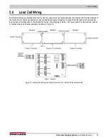
Page 19: ...to the junction box Following conduit work load cell cables are routed through each conduit from the load cells to the junction box All load cell cabling used for this installation comes in the shippi...

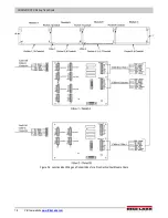
Page 20: ...SURVIVOR OTR Flattop Truck Scale 16 Visit our website www RiceLake com Figure 5 2 Junction Box Wiring and Conduit Runs for a Five Section Four Module Scale...

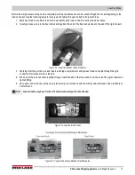
Page 21: ...se to the end of the rigid conduit Figure 5 3 Load Cell Pocket Conduit Installed 3 Working from the junction box end insert a fish tape or similar tool and pull each load cell cable through the rigid...

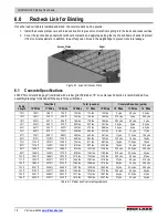
Page 22: ...4 yds 20 ft 304 ft 340 ft 375 ft 203 lbs 227 lbs 251 lbs 4 5 yds 5 yds 5 5 yds 24 ft 367 ft 405 ft 443 ft 245 lbs 270 lbs 296 lbs 5 5 yds 6 yds 6 5 yds 40 ft 608 ft 679 ft 750 ft 406 lbs 454 lbs 501 l...

Page 23: ...te into the inside of the main beams and around the shear connectors Figure 6 2 Junction Box Pocket 3 Strike off and screed the concrete to further settle the concrete and level the surface 4 The firs...

Page 24: ...p the surface moist for seven days is to roll or spray on an epoxy based concrete curing solution immediately after final finishing These epoxy based curing products are available at contractor supply...

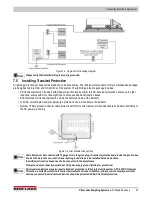
Page 25: ...renches if possible When DC data cables must run in the same trench as AC power lines separate cables as much as possible Figure 7 1 Conduit Run in Trench 7 2 Single Point Ground Conductor A bare 10 g...

Page 26: ...their lines into the building The local utility company can test the resistance of the existing ground rods with a clamp on megohmmeter that measures zero resistance A reading of 3 or less is acceptab...

Page 27: ...r supply surge protector in the AC line before the indicator Number 10 bare ground conductor cable buried in earth from scale frame to DC transient board at indicator and finally to the AC power groun...

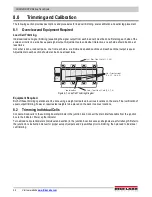
Page 28: ...ne at least twice Figure 8 1 Load Cell Trimming Diagram Equipment Required Both of these trimming operations can be done using a weight cart parked in various locations on the scale Final verification...

Page 29: ...gnal Instead use the individual cell potentiometers for the other three cells to reduce those signals to match the reference cell Remember that all potentiometers were turned to full signal before sta...

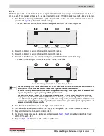
Page 30: ...he indicator reading Repeat this for the last two paired sections cells 3 6 and 4 5 in Figure 8 5 Figure 8 5 Trimming Paired Sections 2 7 3 6 and 4 5 3 Choose the lowest reading of the four as the ref...

Page 31: ...substitution test of an additional 12 5 of the capacity is required This can be the test weight truck bags of sand or any convenient items easy to load onto the scale This total calibration weight of...

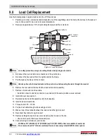
Page 32: ...e two load cell bolts and lift out load cell and link assembly 7 Remove LB connector and flex cable Install LB connector and flex conduit on new load cell in the same position as was removed 8 Install...

Page 33: ...e 10 2 Foundation A truck scale is only as good as the foundation on which it rests Keeping the foundation clean and well drained provides more accurate and dependable vehicle weighing A quick visual...

Page 34: ...the power company Check the Scale Grounding 1 Make sure the scale and all peripherals are connected to a transient protection device such as an uninterruptible power supply to deter voltage distortion...

Page 35: ......

Page 36: ...Canada Mexico 800 321 6703 International 715 234 9171 Europe 31 0 26 472 1319 Rice Lake Weighing Systems is an ISO 9001 registered company Rice Lake Weighing Systems Specifications subject to change w...

Reviews: