background image

48

420HE  Installation Manual

1.10 Regulatory Mode Functions

1.11 LED Functions

The following is a list of diagnostic LEDs for the 

420

Plus

. See Figure 1-3  7 for locations on the 

420 Plus

CPU board. 

Serial Port Status  

LED1 (EDP Port)

Flashing red = TXD activity
Flashing green = RXD activity
On steady or off = No activity

LED2 (PRN Port)

Flashing red = TXD activity
Flashing green = RXD activity
On steady or off = No activity

Power Supply

LED (+5AV)

Excitation/ADC supply on

LED (+5V & +3.3V)

Digital logic supply on

Operation Status

LEDHB (Microprocessor)

Flashing green = Active 
Red = Fault

LED AD (ADC)

Green = Active 
Red = Fault

LED MEM (Memory Test)

Green = Pass 
Red = Fail

LED ANA 

Red = Not Implemented

(Analog Option Card) 

Digital Input/Output Status

DO 1 (Digital Out 1)

On when lit (active low)

DO 2 (Digital Out 2)

On when lit (active low)

DI 1 (Digital In 1)

On when lit (active low)

DI 2 (Digital In 2)

On when lit (active low)

REGULAT

Parameter Value

Weight on Scale

Tare in System

Front Panel Key Function

TARE

ZERO

NTEP

zero or negative

no

no action

ZERO

yes

CLEAR TARE

positive

no

TARE

yes

TARE

CANADA

zero or negative

no

no action

TARE

yes

CLEAR TARE

positive

no

TARE

yes

no action

OIML

zero or negative

no

no action

ZERO

yes

CLEAR TARE

ZERO and CLEAR TARE

positive

no

TARE

ZERO

yes

TARE

ZERO and CLEAR TARE

NONE

zero or negative

no

TARE

ZERO

yes

CLEAR TARE

positive

no

TARE

yes

CLEAR TARE

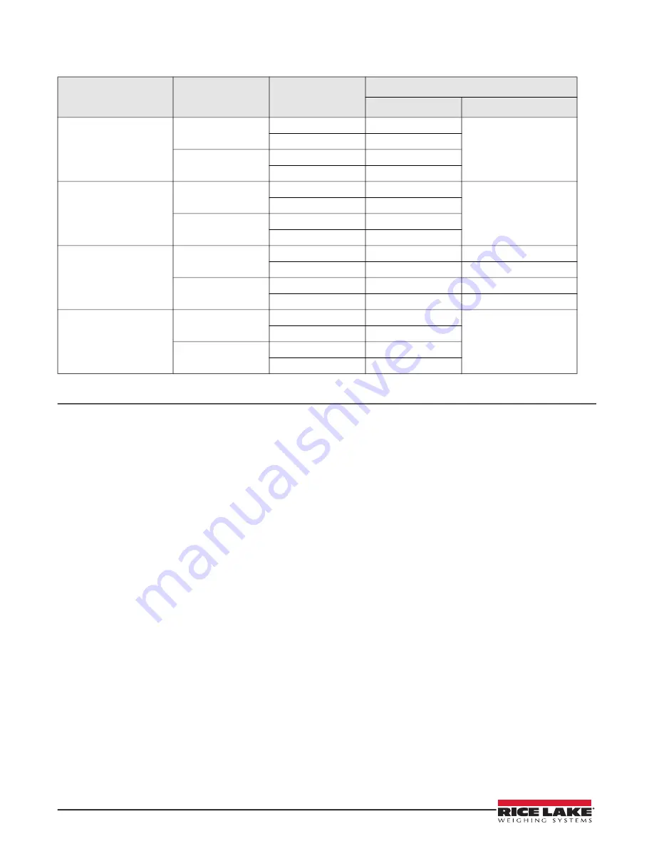
Table 1-8. TARE and ZERO Key Functions for REGULAT Parameter Settings

Summary of Contents for Revolution SURVIVOR 420HE

Page 1: ...87972 Rev B SURVIVOR 420HE Hostile Environment Digital Weight Indicator Version 1 15 Installation Manual...

Page 2: ...marks of their respective companies All information contained within this publication is to the best of our knowledge complete and accurate at the time of publication Rice Lake Weighing Systems reserv...

Page 3: ...Parts 10 1 0 Configuration 13 1 1 Configuration Methods 13 1 1 1 Revolution Configuration 13 1 1 2 EDP Command Configuration 13 1 1 3 Front Panel Configuration 14 1 2 Menu Structures and Parameter De...

Page 4: ...matting 35 1 1 Print Formatting Commands 35 1 2 Customizing Print Formats 35 1 2 1 Using the EDP Port 36 1 2 2 Using the Front Panel 36 1 2 3 Using Revolution 37 1 0 Appendix 38 1 1 Error Messages 38...

Page 5: ...result in damage to equipment or corruption to and loss of data Safety Precautions Do not operate or work on this equipment unless you have read and understand the instructions and warnings in this ma...

Page 6: ...ions 1 1 Operating Modes The 420 Plus has four modes of operation Normal Primary mode Normal mode is the default mode of the indicator The indicator displays gross or net weights as required using the...

Page 7: ...nnunciators and Normal Mode Key Functions 1 3 LED Annunciators The 420 Plus display uses a set of six LED annunciators to provide additional information about the value being displayed Gross and Net a...

Page 8: ...by the Net annunciator 1 4 2 Toggle Units Press the UNITS key to switch between primary and secondary units The appropriate units LED under the display is lit 1 4 3 Zero Scale 1 In gross mode remove a...

Page 9: ...e or setpoint number prompt Press the UP key until SETPNT is displayed Press the UP key once more to exit See Figure 1 2 1 4 9 Turn Setpoint On or Off To turn a setpoint on or off at the front panel e...

Page 10: ...rminals PN 71125 for connectors J2 and J3 and one four position screw terminal PN 71126 for connector J6 see figure 1 3 Three reducing glands PN 15664 One capacity label PN 42350 Three each of groundi...

Page 11: ...ield and the grounding clamp Route stripped cables through cord grips and clamps Ensure shields contact grounding clamps as shown in Figure 1 2 Tighten grounding clamp nuts Finish installation using c...

Page 12: ...ge 13 for configuration information 1 3 4 Digital I O Digital inputs can be set to provide several indicator functions including all keypad functions The inputs are active on with low voltage 0 VDC an...

Page 13: ...Plus Draw Latches and NTEP Seal 1 6 Board Removal If you must remove the 420 Plus CPU board use the following procedure 1 Disconnect power to the indicator 2 Open indicator using draw latches 3 Disco...

Page 14: ...ng 1 13 87958 CPU board 1 15 15655 Cable grips 8 NPT 3 16 15656 Lock nut 8 NPT 3 17 85202 Power cord 120 VAC 1 See Figure 1 6 12 18 87971 Switch assembly 6 pushbutton 1 See Figure 1 5 11 19 87969 Filt...

Page 15: ...11 Figure 1 5 420 Plus Assembly Drawing To Power Supply From Power Supply From Power Supply 1 2 3 4 5 6 7 8 9 10 11 12 13 15 18 19 20 16...

Page 16: ...nual Figure 1 6 420 Plus Assembly Drawing Grounding Detail Ground Wire From Power Cord 17 Ground Screw In Bottom Panel 12 2X Cable Tie Wires Using 2 Holes Provided In Bracket Wire Tie Squares 29 30 28...

Page 17: ...llows configuration data to be retrieved from one indicator edited then downloaded to another To use Revolution do the following 1 Install the Revolution module on an IBM compatible personal computer...

Page 18: ...ad tare function sample rate and digital filtering parameters FORMAT Format Set format of primary and secondary units display rate CALIBR Calibration Calibrate indicator See Section 1 0 on page 27 for...

Page 19: ...of the 420 Plus menu structures In the actual menu structure the settings you choose under each parameter are arranged horizontally To save page space menu choices are shown in vertical columns The fa...

Page 20: ...cluding print tare and zero require the scale to be at standstill Maximum legal value varies depending on local regulations If this parameter is set to 0 the standstill annunciator will be set continu...

Page 21: ...nu Parameters Continued XXXXXXX XXXXXXX XXXXXXX XXXXXXX DSPDIV MULT UNITS DECPNT 0 453592 5D 2D 1D number PRIMAR SECNDR 6SEC 4SEC 3SEC 2 5SEC 2SEC 1 5SEC 750MS 500MS 250MS 8SEC DSPRAT DSPDIV UNITS DEC...

Page 22: ...Secondary Units SECNDR Parameter DECPNT 88888 8 888888 888880 8 88888 88 8888 888 888 8888 88 Decimal point location Determines the location of the decimal point or dummy zeros in the secondary unit d...

Page 23: ...RO Press Enter to remove an offset value from the zero and span calibrations Use this parameter only after WZERO and WSPAN have been set See Section 1 1 on page 27 for more information about using thi...

Page 24: ...Whenever the print key is pressed and data is sent out the word PRINT is momentarily put on the remote display Level 3 Submenus EDP Port and Printer Port BAUD 9600 19200 38400 300 600 1200 2400 4800...

Page 25: ...lows tares to be cleared at any weight value NTEP and OIML modes allow a new tare to be acquired even if a tare is already present In CANADA mode the previous tare must be cleared before a new tare ca...

Page 26: ...COLAN COMMA Specifies the time separator character PROGRM Menu Parameter Choices Description Table 1 6 Program Menu Parameters Continued XXXXXXX XXXXXXX XXXXXXX XXXXXXX GFMT Display rst 6 characters...

Page 27: ...UE number Display and edit the setpoint value TRIP HIGHER LOWER INBAND OUTBND Trips the setpoint when the weight is higher or lower than the setpoint value or is within or outside of the band value LO...

Page 28: ...ue CLRCN resets the consecutive number to the value specified on the CONSTU parameter PROGRM menu KBDLOC disables the keypad while the digital input is held low HOLD holds the current display Releasin...

Page 29: ...fies how the analog output responds to system error conditions Possible values are FULLSC Set to full value 10 V or 20 mA HOLD Hold current value ZEROSC Set to zero value 0 V or 4 mA MIN 000000 number...

Page 30: ...used to check the software version and reg version installed in the indicator You can also check the indicator model Figure 1 14 Version Menu XXXXXXX ALGOUT XXXXXXX XXXXXXX VERS DIGIN SETPNT PROGRM PF...

Page 31: ...calibration weight Use the procedure shown in Figure 1 4 15 to enter the actual value of the test weights to be used for the span calibration Press to store the entered WVAL value and go to span cali...

Page 32: ...the scale Clear the scale and click OK to begin zero calibration If your test weights require hooks or chains place the hooks or chains on the scale for zero calibration 5 When zero calibration is co...

Page 33: ...the keys on the front panel of the indicator Most commands can be used in both setup and weighing mode Several of the commands serve as pseudo keys providing functions that are not represented by a k...

Page 34: ...value Use no spaces before or after the equal sign If you type an incorrect command or value the display reads Changes to the parameters are saved as they are entered but typically do not take effect...

Page 35: ...ue WSPAN Span calibration REZERO Rezero LC CD Set deadload coefficient value LC CW Set span coefficient value Table 1 5 CALIBR EDP Commands Command Description Values EDP BAUD EDP port baud rate 300 6...

Page 36: ...tring See Section 1 0 on page 35 for detailed information NFMT Net demand print format string Table 1 8 PFORMT EDP Commands Command Description Values SP1 SP2 SP1 ENABLE SP2 ENABLE Setpoint enable OFF...

Page 37: ...LGOUT EDP Commands Command Description Response Format UID Set unit ID nnnnnnn SD Set date MMDDYY DDMMYY YYMMDD enter using DATEFMT specified ST Set time hhmm enter using 24 hour format SX Start EDP s...

Page 38: ...arameters to the PC as ASCII formatted text 1 2 2 Downloading Configuration Data from PC to Indicator Configuration data saved on a PC or floppy disk can be downloaded from the PC to an indicator This...

Page 39: ...rint format string includes the output field length of the print formatting commands not the command length For example if the indicator is configured to show a decimal point the G command generates a...

Page 40: ...ing the Front Panel If you have no access to equipment for communication through the EDP port or are working at a site where such equipment cannot be used you can use the PFORMT menu see Figure 1 1 to...

Page 41: ...the formatting commands NL and SP required by the front panel or EDP command methods Using Revolution you can type text directly into the grid then select weight value fields from the tool bar and pl...

Page 42: ...r EACKSM A D calibration checksum error A D converter requires recalibration Call RLWS Service EFCKSM Printer format checksum error Call RLWS Service ELCKSM Load cell calibration checksum error Recali...

Page 43: ...which annunciators are currently displayed on the indicator front panel The ZZ command returns the currently displayed weight and a decimal number representing the LED annunciators currently lit The...

Page 44: ...gure 1 1 Continuous Output Data Format STX POL wwwwwww UNIT G N S TERM ASCII 02 decimal Weight data 7 digits right justi ed with decimal point leading zero supression Overload Underrange Display over...

Page 45: ...46 f 102 66 Ctrl G BEL 07 07 39 27 G 71 47 g 103 67 Ctrl H BS 08 08 40 28 H 72 48 h 104 68 Ctrl I HT 09 09 41 29 I 73 49 i 105 69 Ctrl J LF 10 0A 42 2A J 74 4A j 106 6A Ctrl K VT 11 0B 43 2B K 75 4B...

Page 46: ...B 235 EB 140 8C 1 4 172 AC 204 CC 236 EC 141 8D 173 AD 205 CD 237 ED 142 8E 174 AE 206 CE 238 EE 143 8F 175 AF 207 CF 239 EF 144 90 176 B0 208 D0 240 F0 145 91 177 B1 209 D1 241 F1 146 92 178 B2 210 D...

Page 47: ...ters Figure 1 2 shows the 7 segment LED character set used to display alphanumeric characters on the 420 Plus front panel Figure 1 2 420 Plus Display Characters 9 E Q F R G S 0 H T 1 I U 2 J V 3 K W 4...

Page 48: ...and the secondary decimal point is set to 8888 88 the indicator will overflow if 5 tons or more are applied to the scale With 5 tons applied and a conversion factor of 2000 the secondary units displa...

Page 49: ...4 8 8 With this configuration each A D reading has a 1 in 20 effect on the displayed weight value Setting the filters to 1 effectively disables digital filtering 1 7 2 DFSENS and DFTHRH Parameters Th...

Page 50: ...use more consecutive out of band readings so DFSENS should be set higher to counter low frequency transients Reconfigure as necessary to find the lowest effective value for the DFSENS parameter 1 8 An...

Page 51: ...functions in test mode Note that because the Test Menu functions are all on a single menu level the GROSS NET key has no function Press the ZERO key to exit test mode Table 1 7 summarizes the test me...

Page 52: ...ory Test Green Pass Red Fail LED ANA Red Not Implemented Analog Option Card Digital Input Output Status DO 1 Digital Out 1 On when lit active low DO 2 Digital Out 2 On when lit active low DI 1 Digital...

Page 53: ...age output 0 10 VDC Load resistance 1K minimum Current output 0 20 4 20 mA External loop resistance 500 maximum Digital Specifications Microcomputer Phillips PXAG30K main processor 19 6608 MHz Digital...

Page 54: ...caused by accident misuse neglect alteration improper installation improper repair or improper testing RLWS shall be the sole judge of all alleged non conformities Such equipment has not been modifie...

Page 55: ......

Page 56: ...Rice Lake Weighing Systems 07 19 PN 87972 Rev B...

Reviews: