6
IQ plus 350 Installation Manual
2.3.2
Serial Communications and Digital Inputs
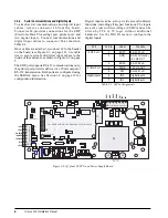
To attach serial communications and digital input
c a b l e s , r e m ove c o n n e c t o r J 4 f r o m t h e b o a r d .
Connector J4 provides connections for the EDP
(Electronic Data Processing) port, printer port, and
two digital inputs. Connect communications and
digital input cables to connector J4 as shown in
Table 2-2.
Once cables are attached, reconnect J4 to the header
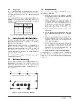
on the board (see Figure 2-6 on page 10). Use cable
ties to secure serial and digital input cables to the
inside of the enclosure as shown in Figure 2-2 on page
5.
The EDP port supports RS-232 communications only;
the printer port provides either active 20 mA output or
RS-232 transmission. Both ports are configured using
the SERIAL menu. See Section 3.0 on page 12 for
configuration information.
Digital inputs can be set to provide several indicator
functions, including all keypad functions. The inputs
are active (on) with low voltage (0 VDC) and can be
driven by TTL or 5V logic without additional
hardware. Use the DIG IN menu to configure the
digital inputs.
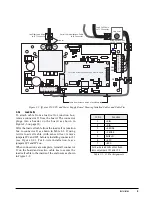
Figure 2-3. IQ plus 350 CPU and Power Supply Board
Port
J4 Pin
Label
Function
EDP Port
1
EDPT
RS-232 TxD
2
GND
RS-232 Ground /
–20 mA OUT
3
EDPR
RS-232 RxD
Printer Port
4
PRMA
+20 mA OUT
5
PRT
RS-232 TxD
Digital Inputs
6
IN2
Digital Input 2
7
IN1
Digital Input 1
Table 2-2. J4 Pin Assignments
C5
C4
L2
L1
C3
C54
C49
C46
C15
C6
C18
C2
C14
C8
C61
C62
C58
C59
C60
C9
C12
C20
C19
U4
R17
R25
R24
R18
R21
R16
R23
R19
SW1
C24
C35
C36
C23
C26
R7
R6
R12
R10
R22
C16
+
C33
+
C21
+
R11
R31
R9
Y2
C28
C29
C31
C32
C27
C7
C13
C10
C11
U1
R2
Q1
R15
R37
U2
D4
C57
C55
C52
C51
C39
C44
C42
C40
C37
C38
C41
C47
C48
C56
C45
C43
R30
RN6
U8
C50
+
Y1
U7
U3
J5
R3
R28
C34
R27
R26
R29
J7
R1
C17
C22
R20
R5
R8
R4
RN3
RN5
RN2
RN1
JP1
JP4
JP2
RN7
RN4
U5
R32
D1
D2
C66
R33
U9
C63
R34
U10
C65
C64
RN8
R35
C67
+
R13
J1
SN
PWR2
J4
ANALOG OUTPUT
+
+
PWR1
F1
1
2
3
4
5
6
7
C1
–EXC
+EXC
SHIELD
–SENSE
+SENSE
–SIG
+SIG
7
6
5
4
3
2
1
LOAD CELL CONNECTOR
TO BACKPLATE-MOUNTED
SETUP SWITCH
SETUP SWITCH
SERIAL COMM & DIGITAL IN
KEYPAD CONNECTOR
F2
D6
D3
D5
12
10
9
7
6
4
3
1
T1
JP7
U6
U11
EDPT
GND
EDPR
PRMA
PR
T
IN2
IN1
LOCATION OF INSTALLED ANALOG OUTPUT MODULE
BROWN
WIRE
BLUE
WIRE
1
J1
2
3
4
JP1
(ANALOG OUT)
JP2
(ANALOG OUT)


