Rice Lake IQ plus 210 Installation Manual Download Page 29

EDP Commands

© 

Rice Lake Weighing Systems


 All Rights Reserved

23

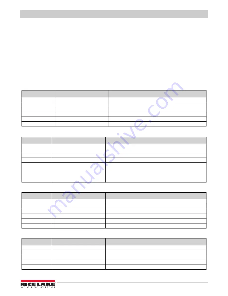
5.1.4 Parameter Setting Commands

Parameter setting commands allow you to display or change the current value for a particular configuration parameter (Tables 

5-3 through 5-8).
Current configuration parameter settings can be displayed in either setup mode or normal mode using the following syntax:

command<ENTER>

Most parameter values only can be changed in setup mode. Use the following command syntax when changing parameter 

values: 

command=value<ENTER>

where 

value

 is a number or a parameter value. Use no spaces before or after the equal (=) sign. If you type an incorrect 

command or value, the display reads 

??

. Changes to the parameters are saved as they are entered but typically do not take 

effect until you exit setup mode. 
For example, to set the motion band parameter to 5, type the following:

MOTBAND=5D<ENTER>

Command

Description

Values

GRADS

Graduations

1–10 000

ZTRKBND

Zero track band

OFF, 0.5D, 1D, 3D

ZRANGE

Zero range

1.9%, 100%

MOTBAND

Motion band

1D, 2D, 3D, 5D, 10D, 20D, OFF

OVRLOAD

Overload

FS+2%, FS+1D, FS+9D, FS

FILTER

Digital filtering

1, 2, 4, 8, 16, 4RT, 8RT, 16RT

Table 5-3.  CONFIG EDP Commands

Command

Description

Values

PRI.DECPNT

Primary units decimal position

8.88888, 88.8888, 888.888, 8888.88, 88888.8, 888888, 888880 (88 88.8 or 888 88 

in LB/OZ display mode)

PRI.DSPDIV

Primary units display divisions

1D, 2D, 5D

PRI.UNITS

Primary units

LB, KG, OZ, G, LB/OZ

ALT.LB

ALT.KG

ALT.OZ

ALT.G

ALT.LBOZ

Enable alternate units

ON, OFF

Table 5-4.  FORMAT EDP Commands

Command

Description

Values

WZERO

Zero calibration

WVAL

Test weight value

test_weight_value

WSPAN

Span calibration

REZERO

Rezero 

LC.CD

Set deadload count

value

LC.CW

Set span count

value

Table 5-5.  CALIBR EDP Commands

Command

Description

Values

EDP.BAUD

Serial port baud rate

1200, 2400, 4800, 9600

EDP.BITS

Serial port data bits/parity

8NONE, 7EVEN, 7ODD

EDP.TERMIN

Serial port termination character

CR/LF, CR

EDP.ECHO

Serial port echo command

OFF, ON

PRNFREQ

Print frequency

DEMAND, AUTO1, AUTO2, STREAM

Table 5-6.  SERIAL EDP Commands

Summary of Contents for IQ plus 210

Page 1: ...IQ plus 210 Digital Weight Indicator Version 1 Installation Manual PN 64640 Rev C August 31 2022...

Page 2: ...respective companies All information contained within this publication is to the best of our knowledge complete and accurate at the time of publication Rice Lake Weighing Systems reserves the right to...

Page 3: ...se descriptions and dates can be viewed at www ricelake com training or obtained by calling 715 234 9171 and asking for the training department Revision History This section tracks and describes manua...

Page 4: ...Repair Parts 7 3 0 Configuration 10 3 1 Configuration Methods 10 3 1 1 Revolution Configuration 10 3 1 2 EDP Command Configuration 11 3 1 3 Front Panel Configuration 11 3 2 Menu Structures and Paramet...

Page 5: ...training or obtained by calling 715 234 9171 and asking for the training department 6 0 Appendix 25 6 1 Error Messages 25 6 1 1 Displayed Error Messages 25 6 1 2 Using the XE EDP Command 25 6 2 Statu...

Page 6: ...210 Installation Manual 3 Visit our website www RiceLake com Rice Lake continually offers web based video training on a growing selection of product related topics at no cost Visit www ricelake com w...

Page 7: ...s of a large 8 in 20 mm six digit seven segment LED display seven LED annunciators and two piezo switches used to zero the scale and select the displayed units Features include Drives up to four 350 l...

Page 8: ...grams lb and oz annunciators are both lit when the displayed weight is in pounds and ounces 1 5 Indicator Operations Basic IQ plus 210 operations are summarized below Zero Scale 1 Remove material from...

Page 9: ...t stand option or bench scale feet jam nuts lock washers and cap screws for column and attachment bracket options To install attach the mounting assembly to scale base then assemble the indicator to t...

Page 10: ...round shielded cables Use the lock washers clamps and kep nuts provided in the parts kit to install grounding clamps on the studs adjacent to the cord grips Install grounding clamps only for cord grip...

Page 11: ...must be set for the type of load cell connected to the indicator For load cells with balanced bridges set the jumper in the OFF position Example of balanced load cells include the RL1040 RL1250 RL126...

Page 12: ...figure the digital inputs See Section 3 2 5 on page 18 for information about configuring the digital inputs 2 3 6 Enclosure Reassembly Once cabling is complete position the backplate over the enclosur...

Page 13: ...8 12 14 2 33 37 3 36 Brown Wire Blue Wire From Line Filter 19 1 20 Detail B Ground Post Assembly 16 Back Panel 35 4 To CPU J1 15 27 24 10 11 9 26 From Inside Bottom Panel See Detail A Detail A Inside...

Page 14: ...11 42640 Setup switch access screw 1 4 x 28NF x 1 4 1 12 41965 Power cord assembly 115VAC 1 45254 Power cord assembly 230VAC 1 13 41964 Line filter assembly 1 14 14621 Kep nuts 6 32NC hex 5 20 15134...

Page 15: ...Plus 210 Tilt Stand Assembly Item No Part No Description Qty 1 29635 Tilt stand 1 2 42149 Tilt stand feet 4 3 15144 Nylon washers 1 4x1x1 16 2 4 30342 Wing knobs 2 Table 2 5 IQ Plus 210 Tilt Stand As...

Page 16: ...1 1 Revolution Configuration The Revolution configuration utility provides the preferred method for configuring the IQ plus 210 indicator Revolution runs on a personal computer to set configuration p...

Page 17: ...izes the functions of each of the main menus Figure 3 2 Front Panel Key Functions in Setup Mode Front Panel Menu Navigation The front panel buttons are used to navigate through the menus in setup mode...

Page 18: ...vel press RIGHT to scroll through the values for the parameter Pressing RIGHT from the last value wraps around to first value Press ENTER to select the value and return to the parameter prompt To edit...

Page 19: ...elect the value and return to the BAUD parameter prompt RIGHT Navigation functions same as BAUD parameter When displaying last parameter prompt press RIGHT to return to the first level menu prompt ENT...

Page 20: ...ro range Selects the range within which the scale can be zeroed The 1 9 selection is 1 9 around the calibrated zero point for a total range of 3 8 Indicator must be at standstill to zero the scale Use...

Page 21: ...ameter DECPNT 888 888 8888 88 88888 8 888888 888880 8 88888 88 8888 or 88 88 8 888 88 Decimal point location Specifies the location of the decimal point or dummy zeroes in the primary unit display Val...

Page 22: ...es Description Level 2 submenus WZERO Display and edit the zero calibration A D count value WVAL Display and edit the test weight value WSPAN Display and edit the span calibration A D count value REZE...

Page 23: ...ransmitted when a positive scale weight is at standstill STREAM Continuous output See Section 6 3 on page 27 for output format Weight data is sent to the serial port in displayed units except when oth...

Page 24: ...the RESET function is performed Figure 3 11 Default Menu 3 2 7 Version Menu The VERS menu is used to check the software version installed in the indicator There are no parameters associated with the...

Page 25: ...lue and return to the WZERO prompt or use the procedure shown in Figure 4 2 to edit the value When done press RIGHT to go to the WVAL prompt 4 With WVAL displayed press ENTER to show the test weight v...

Page 26: ...mmands Once the indicator is connected to the sending device do the following 1 Place the indicator in setup mode display reads CONFIG and remove all weight from the scale platform If your test weight...

Page 27: ...n then click OK 5 The Zero Calibration dialog box prompts you to remove all weight from the scale Clear the scale and click OK to begin zero calibration NOTE If your test weights require hooks or chai...

Page 28: ...sections list the commands and command syntax used for each of these groups 5 1 1 Key Press Commands Key press EDP commands see Table 5 1 simulate pressing the buttons on the front panel of the indic...

Page 29: ...10 000 ZTRKBND Zero track band OFF 0 5D 1D 3D ZRANGE Zero range 1 9 100 MOTBAND Motion band 1D 2D 3D 5D 10D 20D OFF OVRLOAD Overload FS 2 FS 1D FS 9D FS FILTER Digital filtering 1 2 4 8 16 4RT 8RT 16...

Page 30: ...are set up or when an indicator is replaced To download configuration data connect the PC to the EDP port as described in Section 5 2 1 Place the indicator in setup mode and use the PC communications...

Page 31: ...0111 1111 Using the bit assignments in Table 6 2 this value indicates all tests were run Error Message Description Solution E A D A D physical error Call Rice Lake Weighing Systems Rice Lake Weighing...

Page 32: ...eturned data is wwwwww zzz where wwwwww is the current displayed weight zzz is the annunciator status value see Table 6 3 If more than one annunciator is lit the second number returned is the sum of t...

Page 33: ...m DC Power PN 15888 12 24 AWG 0 276 7 mm Table 6 4 Recommended Wire Gauge Specifications Cord Grip Diameter Range PG9 PN 15626 0 138 0 315 3 5 8 mm PG11 PN 68600 0 197 0 394 5 10 mm Table 6 5 Cord Gri...

Page 34: ...ed by capacitor bypass Digital Specifications Digital Inputs 2 inputs TTL or switch closure active low Digital Filter Software selectable Serial Communications Serial Port Full duplex RS 232 9600 4800...

Page 35: ......

Page 36: ...nada Mexico 800 321 6703 International 715 234 9171 Europe 31 0 26 472 1319 Rice Lake Weighing Systems is an ISO 9001 registered company Rice Lake Weighing Systems Specifications subject to change wit...

Reviews: