background image

Assembly

© Rice Lake Weighing Systems


 All Rights Reserved

5

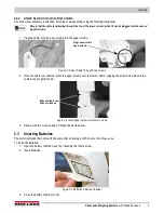
2.2.2 Attach Second Column to First Column

Once the wheel assembly is attached, finish the scale assembly using the following instructions.

Ensure that the cable is extending through the top of the lower column so that it can be plugged into the second 

(upper) column.

1. Plug the cable from the lower column into the upper column.

Figure 2-5. Extend Cable Through Scale Column

2. Once the cable is connected, place the upper column onto the lower column, aligning the screw holes. Ensure the 

cable does not get pinched.

Figure 2-6. Insert Upper Column into Lower Column

3. Secure with two screws using a Phillips head screwdriver. 

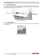
2.3 Inserting Batteries

The six AA batteries that come with the scale offer an average of 25 hours of continuous use. 

To install the batteries:

1. Open the battery chamber cover by loosening the thumb screw. 

2. Insert batteries.

Figure 2-7. Batteries in Battery Chamber 

3. Close the battery chamber cover. 

Note

Plug connector into 

upper column

Make sure that screw 

holes are lined up

Summary of Contents for 150-10-6

Page 1: ...150 10 6 Digital Physician Scale Waist Level Software Version 11525 Technical Manual PN 162342 Rev B August 18 2022...

Page 2: ...respective companies All information contained within this publication is to the best of our knowledge complete and accurate at the time of publication Rice Lake Weighing Systems reserves the right to...

Page 3: ...ing or obtained by calling 715 234 9171 and asking for the training department Revision History This section tracks and describes the current and previous manual revisions for awareness of major updat...

Page 4: ...Connections 6 2 5 Leveling the Scale 6 3 0 Operation 7 3 1 Weighing 8 3 2 Hold Release Function 8 3 3 Using the Body Mass Index BMI Function 8 3 4 Troubleshooting 9 4 0 Configuration 10 4 1 General N...

Page 5: ...is operated in a commercial environment This equipment generates uses and can radiate radio frequency energy and if not installed and used in accordance with the instruction manual may cause harmful i...

Page 6: ...t the scale while someone is on the scale Do not allow minors children or inexperienced persons to operate this scale Do not use in the presence of flammable materials Do not use this product if any o...

Page 7: ...back Damage caused by improper packaging is not covered by the warranty 2 2 Scale Assembly Use the following steps to set up the scale A Phillips head screwdriver will be needed for installation 1 Pla...

Page 8: ...attach the column to the scale base as shown in Figure 2 3 Figure 2 3 Attach With Screws 2 2 1 Wheel Assembly Attach the wheel assembly to the scale prior to connecting the second column To attach th...

Page 9: ...lumn 2 Once the cable is connected place the upper column onto the lower column aligning the screw holes Ensure the cable does not get pinched Figure 2 6 Insert Upper Column into Lower Column 3 Secure...

Page 10: ...gure 2 8 Rice Lake Weighing Systems offers optional AC adapters utilizing an adapter not supplied by Rice Lake Weighing Systems voids all warranties Figure 2 8 Power Connection 2 5 Leveling the Scale...

Page 11: ...ff the scale A second press releases the weight value Not active while in BMI mode BMI Pressing the BMI key enables access to the BMI Body Mass Index mode defaults when scale is turned on The patient...

Page 12: ...to zero Pressing prior to the patient getting on the scale will also hold the weight display 3 3 Using the Body Mass Index BMI Function Use the following steps in determining the BMI LB Mode 1 Ensure...

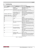
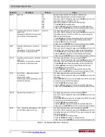
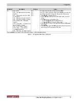
Page 13: ...le E4L BAT Battery low but still usable one bar left on indicator display E4U Battery low and unstable no bars left on indicator display E11 CAL Calibration Error recalibrate scale Err 1 Load cell cab...

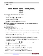
Page 14: ...Press to enter a displayed menu and or parameter Press or to scroll through values Press to save the displayed selection and move to the next parameter 4 1 2 Enter Numbers Press to enter parameter va...

Page 15: ...cated in the back of the scale to enter the setup parameters for the scale Use a small paper clip small screwdriver or other similar object to press the setup switch 4 Once the setup switch is pressed...

Page 16: ...6 Use the Up Down arrow keys to increment decrement numbers 7 When done press ENTER key to move to the next parameter LOAD LOAD This is the amount of weight applied during calibration Can also be chan...

Page 17: ...umeric value and ARW If you do not want to change this value press the BMI key to move to the next setting Example from ARW to SAL If you want to change the value use the following steps 1 Press ENTER...

Page 18: ...een a numeric value and ATOUT If you do not want to change this value press the BMI key to move to the next setting If you want to change the value use the following steps 1 Press ENTER key to change...

Page 19: ...ant to change this value press the BMI key to move to the next settings If you want to change the value use the following steps 1 Press ENTER to change parameters 2 Use the Up Down arrow keys to selec...

Page 20: ...e back of the scale to enter the setup parameters for the scale Use a small paper clip small screwdriver or other similar object to press the setup switch on the back of the indicator under the cover...

Page 21: ...le until ID flashes 2 Press Press to access the test menu 3 Continue to press to scroll through the various menu items 4 Once complete press until Done displays 5 Press to start the weighing process F...

Page 22: ...as the weight was either in motion or out of range If displaying weight and not BMI the scale will send out the following 21 character string xxxxxxxxx SP uu SP mmmmm SP CR LF Table 5 1 Print Format T...

Page 23: ...rotocol Commands Name ESC Character ESC Value with Parameters Description Reading R R Tells PC the scale is sending a reading immediately following this is the value that is sent Example ESC R ESC W02...

Page 24: ...D Z Zero the scale F Show flash values used for the first flash process L USB On Off not available on USB communication Table 5 5 Maintenance Protocol Commands Escape Protocol Example 1 Escape Protoco...

Page 25: ...the use of the USB driver Driver protections may need to be temporarily disabled on Windows 10 or later computers to allow for the installation of the USB driver 1 Connect the scale s indicator to a P...

Page 26: ...personnel Go through the following steps for basic maintenance Check the overall appearance of the entire scale for any obvious signs of damage Inspect the condition of the AC power adapter cord for...

Page 27: ...table baud rate default 9600 8 bits No parity 1 stop bit No handshaking Environmental Operating Temperature 50 F to 104 F 14 C to 40 C Storage Temperature 32 F to 158 F 0 C to 70 C Humidity 85 relativ...

Page 28: ...150 10 6 Digital Physician Scale 24 Visit our website www RiceLake com...

Page 29: ......

Page 30: ...54868 USA U S 800 472 6703 Canada Mexico 800 321 6703 International 715 234 9171 Europe 31 0 26 472 1319 Rice Lake Weighing Systems Specifications subject to change without notice www ricelake com PN...

Reviews: