9
9
I
NSTALLATION SEQUENCE WITH METALLIC PIT
1 - Ensure that the laying point of the STOPPER T does not fall within an impluvium area; in cases when, no matter why, this circumstance occurs, you
need to partially shelter the STOPPER T by means of a draining channel, equipped with covering grid.
2 - Dig a hole (using a miniature excavator or your hands) down to
1,30 m
in depth approx. A sector side shall be
1 m
approx.
3 - Ensure that the ground features a good water absorption (try by introducing about 40 litres of water and rate that the drain takes place in less than
30 minutes); otherwise, drain rain water through a pipe that is 60 mm in diameter connected to the sewer or, as an alternative, connected to a
pit (equipped with a pumpdown system, such as, for instance, an electric pump) being deeper than the cement pipe that collects and drains rain
water).
4 - Introduce gravel (grain 8 to 20 mm in diameter approx.) until a thickness of
30 cm
approx. is reached, taking care to compress it well to avoid eventual
“settling shrinkages”.
5 - Lay on the gravel the metallic pit complete with counter frame, paying attention that it has to be parallel to a plumb line and that the upper level of the
counter frame should be about 10 mm above the walking level (in order to reduce the flowing in of raining water).
Further on, please pay attention
on the counter frame setting considering the traffic direction (see drawing enclosed).
6 - Once the metallic pit is laid and if the bollard is equipped of inbuilt blinker and/or heating devices (optional articles), lay a flexible sheath with diameter
50 mm from the connection foreseen in metallic pit to the devices control panel.
7 - Introduce concrete all around the metallic pit thus made until its top is reached (about -10 cm from the walking level): Please pay attention that the
special clamps delivered with the counter frame are well placed. Once the metallic pit is laid, carry out the finish work using the same material as
the road course that is found all around the counter frame.
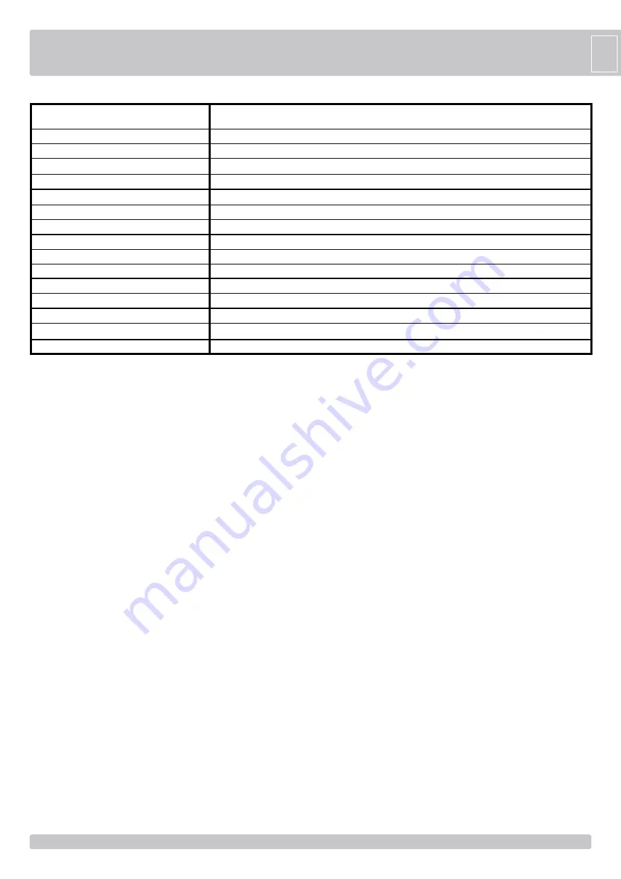
TECHNICAL DATA
Moving criteria
Moving cylinder
Moving cylinder treatment
Moving cylinder diameter
Moving cylinder height
Upper part of the cylinder (head)
Upper part of the cylinder treatment
Protection class
Work frequency - resistance class
Adesive reflecting strip
Temperature range of duty
Weight of the bollard with pit
Shock resistance
Breaking resistance
Pit dimensions
Single effect actuator
Steel FE37 - thickness 6 mm
Polyester powder painting - color metalized dark gray RAL7021
275 mm
600 mm
Anticorodal cemented alluminium
Polyester powder painting - color grey anthracite RAL9006
IP 67
Intensive use > 2.000.000 movings - 2.000 daily movings
Standard altezza 55 mm
-15°C +70°C - Optional: heating devices for temperature up to -25°C
kg 154
9.000 joule
120.000 joule
560 x 560 x H 1020 mm
STOPPER T 275 SEMI-AUTOMATIC - STEEL 6 mm
STOPPER T 275 SA INSTALLATION
G
B
Summary of Contents for AA51213
Page 14: ...14 14 NOTES ...


