background image

© 2004

Alamo Group Inc.

MAINTENANCE

MAINTENANCE

F-3778-12-04

Maintenance Section 5-7

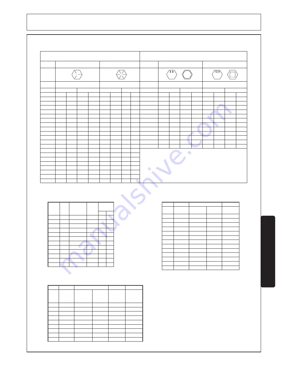
GENERAL TORQUE SPECIFICATIONS

USE THE FOLLOWING TORQUES WHEN SPECIAL TORQUES ARE NOT GIVEN

AMERICAN STANDARD CAP SCREWS

METRIC CAP SCREWS

SAE

Cap

Grade

Size

Inches

MIN

MIN

MIN

MIN

MIN

MAX

MAX

MAX

MAX

MAX

MIN

MAX

MIN

MIN

MAX

MAX

FT-LBS

FT-LBS

N·m

FT-LBS

N·m

N·m

FT-LBS

N·m

Size

Millimeters

1/4-20

6.25

12

9

8

6

7.25

15

11

11

8

8.5

10

8.25

11

9.5

13

M6 x 1.00

1/4-28

8

31

23

21.5

16

9

36.5

27

27

20

11

12

10.5

14

12

16

M8 x 1.25

5/16-18

14

57

42

39

29

15

70

52

47

35

19

20

18.5

25

20

27

M10 x 1.50

5/16-24

17.5

102

75

70

52

19

123

91

84

62

23

26

23

31

25

34

M12 x 1.75

3/8-16

26

163

120

115

85

28

198

146

139

103

35

38

35

47.5

37

50

M14 x 2.00

3/8-24

31

238

176

176

130

34

293

216

214

158

42

46

41

55.5

45

61

M16 x 2.50

7/16-14

41

325

240

233

172

45

398

294

284

210

55.5

61

55

74.5

60

81

M18 x 2.50

7/16-20

51

465

343

335

247

55

577

426

408

301

69

74.5

68

92

75

102

M20 x 2.50

1/2-13

65

639

472

450

332

72

780

576

547

404

88

97.5

86

116

96

130

M22 x 2.50

1/2-20

76

812

599

573

423

84

992

732

700

517

103

114

102

138

112

152

M24 x 3.00

9/16-12

95

1217

898

863

637

105

1488

1098

1055

779

129

142

127

172

140

190

M27 x 3.00

9/16-18

111

1658

1224

1181

872

123

2027

1496

1444

1066

150

167

148

200

164

222

5/8-11

126

139

171

188

168

228

185

251

5/8-18

152

168

206

228

203

275

224

304

3/4-10

238

262

322

355

318

431

350

474

3/4-16

274

305

371

409

365

495

402

544

7/8-9

350

386

474

523

466

631

515

698

7/8-14

407

448

551

607

543

736

597

809

1-8

537

592

728

802

716

970

790

1070

1-14

670

740

908

1003

894

1211

987

1337

M30 x 3.00

10.9

8.8

Metric Class

Screw

Cap Screw

Typical

Grade ID
Markings

on Head

Typical

Grade ID
Markings

on Head

8

5

TORQUE

TORQUE

TORQUE

TORQUE

NOTE:


These values apply to fasteners as 

received from supplier, dry or when lubricated 
with normal engine oil. They do not apply if 
special graphite or molydisulphide greases or 
other extreme pressure lubricants are used.

Torque Specifications for 

37° JIC Fittings

Torque Specifications for 

SAE O-Ring Fittings

Size

-4

140 ± 10

12 ± 1

2

2

7/16-20

-5

180 ± 15

15 ± 1

2

2

1/2-20

-6

250 ± 15

21 ± 1

1 1/2

1 1/4

9/16-18

-8

550 ± 25

45 ± 5

1 1/2

1

3/4-16

-12

1000 ± 50

85 ± 5

1 1/4

1

1 1/16-12

-16

1450 ± 50

120 ± 5

1

1

1 5/16-12

-20

2000 ± 100

170 ± 10

1

1

1 5/8-12

-24

2400 ± 150

200 ± 15

1

1

1 7/8-12

-32

3200 ± 200

270 ± 20

1

1

2 1/2-12

in.·lb.

Assembly Torque

ft.·lb.

Tube 

Connection 

F.F.F.T

Thread 

Size

Swivel Nut 

or Hose 

Connection 

F.F.F.T

Assembly Torque

Size

2

5/16-24

90 ± 5

7.5 ± 0.5

1 ± .25

3

3/8-24

170 ± 10

14 ± 1

1 ± .25

4

7/16-20

220 ± 15

18 ± 1

1 ± .25

5

1/2-20

260 ± 15

22 ± 1

1 ± .25

6

9/16-18

320 ± 20

27 ± 2

1.5 ± .25

8

3/4-16

570 ± 25

48 ± 2

1.5 ± .25

10

7/8-14

1060 ± 50

90 ± 5

1.5 ± .25

12

1 1/16-12

1300 ± 50

110 ± 5

1.5 ± .25

14

1 3/16-12

1750 ± 75

145 ± 6

1.5 ± .25

16

1 5/16-12 1920 ± 125

160 ± 6

1.5 ± .25

20

1 5/8-12

2700 ± 150

225 ± 12

1.5 ± .25

24

1 7/8-12

3000 ± 150

250 ± 12

1.5 ± .25

32

2 1/2-12

3900 ± 200

325 ± 15

1.5 ± .25

F.F.F.T.

in.·lb.

ft.·lb.

Swivel Nut 

or Hose

O-Ring Face Seal Hose/ 

Tube Swivel Nut

Swivel Nut 

Torque

Swivel 

Nut Hex 

Size 

(in.)

Thread 

Size 

(in.)

Dash 

Size

-3

-4

-5

-6

-8

-10

-12

-14

-16

-20

-24

-32

5

6

8

10

12

16

20

22

25

32

38

50.8

--

9/16 - 18

--

11/16 - 16

13/16 - 16

1 - 14

1-3/16 - 12

1-3/16 - 12

1-7/16 - 12

1-11/16 - 12

2 - 12

--

--

11/16

--

13/16

15/16

1-1/8

1-3/8

--

1-5/8

1-7/8

2-1/4

--

--

16

--

24

50

69

102

102

142

190

217

--

--

N·m lb

f

·ft

12

--

18

37

51

75

75

105

140

160

--

Metric 

Tube 

O.D. 

(mm)

Summary of Contents for RHINO 7214 MSL

Page 1: ...lished 12 04 Part No F 3778 7214 MSL Loader OPERATOR S MANUAL This Operator s Manual is an integral part of the safe operation of this machine and must be maintained with the unit at all times READ UN...

Page 2: ...of the Machine is recorded on the Warranty Card and on the Warranty Form that you retain The use of will fit parts will void your warranty and can cause catastrophic failure with possible injury or d...

Page 3: ...4 1 Preparing Tractor Operating Loader Filling Bucket 4 2 Lifting Load Carrying Load Dumping Bucket Lowering Bucket 4 3 Operating Float Control Loading From Bank 4 4 Peeling Scraping Loading Truck Sp...

Page 4: ...2004 Alamo Group Inc SAFETY SECTION Safety Section 1 1...

Page 5: ...in proper stability Always carry bucket or attachment as low as possible 5 Allow for loader length when making turns 6 Stop loader arms gradually when lowering or lifting 7 Use caution when handling l...

Page 6: ...and legible When transporting the Equipment use the Power Unit flashing warning lights and follow all local traffic regulations Operate this Equipment only with a Tractor equipped with an approved rol...

Page 7: ...r and all support personnel should wear hard hats safety shoes safety glasses and proper hearing protection at all times for protection from injury including injury from items thrown by the equipment...

Page 8: ...eed in turns Increase the speed through the turn only after you determine that it is safe to operate at a higher speed Use extreme care and reduce your speed when turning sharply to prevent the Power...

Page 9: ...while operating the Power Unit and Implement Drugs and alcohol will affect an operator s alertness and coordination and therefore affect the operator s ability to operate the equipment safely Before o...

Page 10: ...pair work on the implement Place the Loader on the ground or securely supported on blocks or stands disengage the auxiliary hydraulics and turn off engine Push and pull the control levers several time...

Page 11: ...SAFETY SAFETY O P E R A T O R S MAN U A L IN SID E 8 6 4 5 3 8 2 3 5 6 13 13 1 9 9 L C LEFT SIDE OF LOADER RIGHT SIDE OF LOADER MANUAL CANISTER LEFT SIDE LEFT MID MOUNTING BRACKET 7 10 12 11 F 3778 12...

Page 12: ...der Removal Reinstallation Safety 6 49703 2 MODEL 7214 7 48858 1 DANGER Electric Shock 8 35674 5 2 STRIPE White 54 9 48322 2 DANGER Support Loader 10 47730 1 WARNING Handling Bales Do Not Carry People...

Page 13: ...rious injury or death 48858 DANGER 7 48858 5 51902 WARNING LOADER SAFETY Know all operation warning and safety instructions in the operator s manual before operating the loader Replacement manuals are...

Page 14: ...2004 Alamo Group Inc SAFETY 1 49695 6 49703 8 35674 5 SAFETY O P E R A T O R S MAN U A L INSIDE 13 00776031 2 51447 F 3778 12 04 Safety Section 1 11...

Page 15: ...t with which the employee is or will be involved Employer Responsibilities To ensure employee safety during Tractor and Implement operation it is the employer s responsibility to 1 Train the employee...

Page 16: ...2004 Alamo Group Inc INTRODUCTION SECTION Introduction Section 2 1...

Page 17: ...to tractor NOTE This safety alert symbol identifies important safety messages in this manual Observe and follow all safety messages to prevent personal injury Reference to left hand and right hand use...

Page 18: ...Time 6 6 sec Lowering Time 4 6 sec Attachment Dumping Time 3 0 sec Attachment Rollback Time 2 9 sec Weight w Average Mounting Kit Hose Kit and 96 HD Material Bucket 3603 Lift Cylinder Stroke 28 88 in...

Page 19: ...2004 Alamo Group Inc ASSEMBLY SECTION Assembly Section 3 1...

Page 20: ...m loader upright Remove tarp strap securing loader hoses from tractor handrail 7 Start tractor engine and release brakes Retract bucket cylinders to allow parking stands to contact ground WARNING It i...

Page 21: ...in saddles see Figure D Extend tilt cylinders to FULLY seat both loader upright pins into mount pin saddles and raise parking stands off ground Retract lift cylinders allowing tractor to move forward...

Page 22: ...attachment NOTE If bucket or attachment is not securely attached follow instructions for detaching then repeat above procedure DISMOUNTING QUICK ATTACH BUCKET OR OPTIONAL ATTACHMENT FROM LOADER WARNI...

Page 23: ...2004 Alamo Group Inc OPERATION SECTION Operation Section 4 1...

Page 24: ...ader and rated load is on rear wheels when bucket contains rated load and is in maximum forward position Sufficient weight can be added to tractor by filling rear wheels with liquid ballast installing...

Page 25: ...treme care when operating loader on a slope keep bucket as low as possible This keeps center of gravity low and will provide maximum stability CAUTION Operating loader on a hillside is dangerous Extre...

Page 26: ...a forward gear that provides sufficient ground speed for loading Exercise caution when undercutting high banks Dirt slides can be dangerous Load from as low as possible for maximum efficiency Loader...

Page 27: ...t LOADING LOW TRUCKS OR SPREADERS FROM A PILE For faster loading minimize angle of turn and length of run between pile and spreader Backgrade occasionally with a loaded bucket to keep working surface...

Page 28: ...eavy objects such as large round or rectangular bales logs and oil drums is not recommended 2 Handling large heavy objects can be extremely dangerous due to Danger of tractor rolling over Danger of up...

Page 29: ...to clear ground when moving Ballast tractor rear to compensate for load Never lift large objects with equipment that does not have an anti rollback device Move slowly and carefully avoiding rough ter...

Page 30: ...OADING INTO TUB GRINDER Lift bucket high enough to clear tub grinder sides Move tractor toward tub grinder to position load near center Extend bucket cylinders to position bucket in dump attitude Grad...

Page 31: ...r loader and grapple fork to knock material down from top of pile so it can be loaded from ground Exercise caution when undercutting a high pile Avalanching material can be dangerous When loading mate...

Page 32: ...bale spear upward to prevent bale from falling off of spear Carry bales as low to the ground as possible to allow maximum visibility and avoid tipping WARNING Because of size and weight of large bales...

Page 33: ...raising the boom with attachment fully dumped The attachment contacts dump stops on underside of front ends of boom While raising boom MSL system pushes attachment tighter against dump stops and tilt...

Page 34: ...2004 Alamo Group Inc MAINTENANCE SECTION Maintenance Section 5 1...

Page 35: ...of each pin accessible from outside the loader Repair hydraulic oil leaks promptly to avoid loss of oil and serious personal injury from escaping oil Replace hoses immediately if they are damaged by a...

Page 36: ...ge and replace if necessary LIFT CYLINDER REASSEMBLY NOTE Be careful not to damage seals and o rings on edges or holes in cylinder tube Inspect and remove burrs and sharp edges if necessary before rea...

Page 37: ...ings 11 support rings 12 and seal 13 from outside groove of piston 10 11 Clean all parts including cylinder tube in suitable cleaning solvent then use air pressure to blow away any dirt or excess solv...

Page 38: ...and piston seals Turn tube 1 horizontal and secure in vise Turn shaft piston and head assembly so hole in shaft 3 is horizontal and slide into cylinder guiding rod into head 8 12 Lubricate o ring 15 a...

Page 39: ...umps or uncurls when control valve is in neutral 1 Control valve spool is leaking 1 Contact your Dealer 2 Control linkage binding 2 Inspect adjust or repair linkage 3 Cylinder seals bypassing oil 3 Re...

Page 40: ...70 790 1070 1 14 670 740 908 1003 894 1211 987 1337 M30 x 3 00 10 9 8 8 Metric Class Screw Cap Screw Typical Grade ID Markings on Head Typical Grade ID Markings on Head 8 5 TORQUE TORQUE TORQUE TORQUE...

Page 41: ...reasonable amount as determined by Manufacturer and for returning the goods to the Dealer whether or not the claim is approved Purchaser is responsible for the transportation cost for the goods or pa...

Page 42: ...o abuse or mis use and have been properly maintained as noted NOTE properly maintained specifically includes but is not limited to A Regular lubrication B Using proper amounts of correct hydraulic flu...

Page 43: ...ently to confine the employee to the protected area provided by the ROPS REQUIRED OF THE OPERATOR 1 Securely fasten seatbelt if the tractor has a ROPS 2 Where possible avoid operating the tractor near...

Page 44: ...7214 MSL SOM 12 04 Printed In U S A P N F 3778...

Reviews: