background image

13

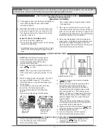
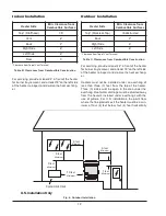
from or one (1) foot above any door, window or gravi-

ty inlet to a building. The top surface of the heater shall

be at least three (3) feet above any forced air inlet, or

intake ducts located within ten (10) feet horizontally.

For installations in Canada, pool heaters shall not be

installed with the top of the vent assembly within 10

feet below, or to either side, of any opening into the

building. Refer to the latest revision of CAN/CGA-

B149.

Outdoor Heaters

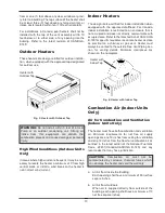
These heaters are design certified for outdoor installa-

tion, when equipped with the approved top designated

for outdoor use.

High Wind Conditions (Outdoor Units

Only)

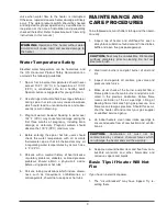
In areas where high winds are frequent, it may be nec-

essary to locate the heater a minimum of 3' from high

vertical walls, or install a wind break so the heater is

not in direct wind current.

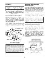
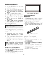
Heater with

Outdoor Top

Fig. 5: Heater with Outdoor Top

WARNING:

Do not install within 3 feet of a Heat

Pump or an outdoor condensing unit. Strong air

intake from this equipment can disturb the

combustion process and cause damage or personal

injury.

Indoor Heaters

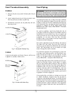
The design is also certified for indoor installation when

equipped with the approved drafthood. For Canada,

indoor installation is restricted to an enclosure that is

not occupied and does not directly communicate with

occupied area. Refer to the latest edition of CAN/ CGA

B-149 for specific requirements.Locate heater as close

as practical to a chimney or gas vent. Heater must

always be vented to the outside. See Vent Piping sec-

tion for venting details. Minimum clearances are

shown on the nameplate.

Combustion Air (Indoor Units

Only)

Air for Combustion and Ventilation

(Indoor Units Only)

The heater must have both combustion and ventilation

air. Minimum requirements for net free air supply

openings are one 12 inches from ceiling for ventilation

and one 12 inches from the floor for combustion air as

outlined in the latest edition of the National Fuel Gas

Code, Z223.1(Canada-CAN/CGA B-149) and any

local codes that may have jurisdiction.

a. All Air from Inside the Building:

Each opening shall have a minimum of 50 net free

square inches.

b. All Air from Outdoors:

When air is supplied directly from outside of the

building, each opening shall have a minimum of 13

net free square inches.

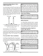
Heater with

Indoor Top

Fig. 6: Heater with Indoor Top

CAUTION:

Combustion air must not be

contaminated by corrosive chemical fumes which

can damage the heater and void the warranty.

Summary of Contents for Versa Spa Heaters

Page 1: ...r appliance To do so may result in an explosion or fire WHAT TO DO IF YOU SMELL GAS Do not try to light any appliance Do not touch any electrical switch do not use any phone in your building Immediate...

Page 2: ...2 Rev 22 reflects the following Changes to Fig 20 and 21 on page 19 The addition of A caution note to page 19...

Page 3: ...10 Receiving Equipment 10 General Specifications 11 INSTALLATION 11 Code Requirements 11 Base Installation 11 Clearances 11 Outdoor Heaters 13 Indoor Heaters 13 Combustion Air Indoor Units Only 13 Ven...

Page 4: ...to the heater WARNING CALIFORNIA PROPOSITION 65 This product contains chemicals known to the State of California to cause cancer birth defects or other reproductive harm CAUTION Verify proper operatio...

Page 5: ...ater providing the water is balanced Automatic chemical dosing devices and salt chlo rinators are usually more efficient in heated water unless controlled they can lead to excessive chlo rine level wh...

Page 6: ...and burner The flame should be blue with a well defined pattern A yellow or floating flame indicates restricted air openings or incorrect orifice size Should this occur shut the heater off and contact...

Page 7: ...way and hold in Immediately place flame to pilot to light Continue to hold control knob in for about 1 minute after the pilot is lighted release knob and it will pop back up Pilot should remain lighte...

Page 8: ...ance is equipped with an ignition device which automatically lights the pilot Do not try to light the pilot by hand B BEFORE OPERATING smell all around the appliance area for gas Be sure to smell next...

Page 9: ...s advice before using pools or hot tubs 6 Persons taking medications which induce drowsi ness such as tranquilizers antihistamines or anticoagulants should not use spas or hot tubs MAINTENANCE AND CA...

Page 10: ...F can seriously damage the heater and will void the warranty For cold climate areas please follow the winterizing procedures listed below Winterizing the Spa Heater When heaters installed outdoors in...

Page 11: ...accordance with local codes or in the absence of local codes with the latest editions of the National Fuel Gas Code ANSI Z223 1 and the National Electrical Code ANSI NFPA 70 for Canada the latest edi...

Page 12: ...and at least 18 on the left side of the heater to inspect and de lime the heat exchang er Heaters must not be installed under an overhang of less than three 3 feet from the top of the heater Three 3...

Page 13: ...llation when equipped with the approved drafthood For Canada indoor installation is restricted to an enclosure that is not occupied and does not directly communicate with occupied area Refer to the la...

Page 14: ...should be securely guyed or braced to withstand snow and wind loads We recommend use of insulated vent pipe spacer through the roofs and walls For protection against rain or blockage by snow the vent...

Page 15: ...testing of that system at test pressures in excess of 1 2 psig 3 45 kPa Dissipate test pressure in the gas supply line before reconnecting the heater and its manual shut off valve to gas supply line F...

Page 16: ...installation is plumbed as follows 1 The inlet side of the filter is plumbed directly to the discharge side of the filter pump 2 The outlet side of the filter is then plumbed to the inlet of the heate...

Page 17: ...d have an anti siphoning device to prevent chemical backup into the heater when the pump is shut off Unitherm Governor Operation The patented Unitherm Governor is a thermostatic mixing valve specifica...

Page 18: ...ittent Ignition Device IID System The Electronic Intermittent Ignition Device automati cally lights the pilot and main burners upon a call for the heat The heater is supplied with a dual voltage trans...

Page 19: ...40V operation 120V ATMOSPHERIC HEATER 120V LOW NOx HEATER SUPPLY SIDE RETURN or NEUTRAL HEATER 4 WIRES H GROUND L L1 RED BLACK B HOT BLACK GREEN GREEN WHITE WHITE Fig 20 120V Wiring 240V ATMOSPHERIC H...

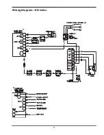
Page 20: ...20 Wiring Diagram Millivolt Units with Mechanical Thermostat IN OUT If required by local code install at this location...

Page 21: ...21 Wiring Diagram IID Units BL BL BL...

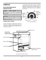
Page 22: ...ng the knobstop ring to the desired location and retightening the set screw Drain Valve Solid State Thermostat Ignition Control Pressure Switch Burner Pilot Thermal Fuse HIGH LIMITS Located in the Inl...

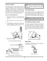
Page 23: ...flow on the low speed is insuffi cient to operate the heater This is apparent when the pressure switch cannot be further adjusted or if the heater makes banging noises In these cases the pump must be...

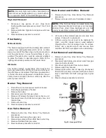
Page 24: ...emove burner tray See Burner Tray Removal procedure 2 Disconnect pilot tubing from gas valve 3 Remove gas valve with manifold from burner tray 4 Remove manifold from gas valve 5 Reverse above procedur...

Page 25: ...tely from between fins Avoid excessive water against refractory Combustion Chamber Removal 1 Remove heat exchanger See Heat Exchanger Removal procedure 2 Lift up and remove front and rear refractory s...

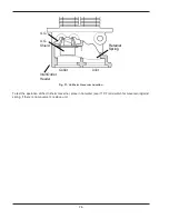
Page 26: ...nlet Inlet Outlet Header Retainer Spring Fig 31 Unitherm Governor Location To test the operation of the Unitherm Governor place in hot water over 110 F and watch for movement against spring If there i...

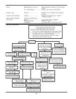
Page 27: ...heat exchanger g n i t o o S Highflowrates Reduce by adding manual bypass valve and adjust by putting thermometer in header 1 4 NPT drain opening Set bypass so thermom eter reads between 105 and 110...

Page 28: ...emain lit attach millivolt meter and read pilot output If below 500millivolt check gas pressure Also check for insects or debris in the pilot burner If main burner fires remove jumper Replace gas valv...

Page 29: ...nd wire Clean flame rod Check electrical connections between flame rod and module Check for cracked ceramic flame rod insulator Check that pilot flame covers flame rod and is steady and blue Adjust pi...

Page 30: ...21 5 28 5 V Check transformer 120 V supply correct as necessary TEMPERATURE 105 106 F Control ok RESISTANCE 0 OHMS SHORT CIRCUIT Check system for shorted wires or open circuits Replace sensor if neces...

Page 31: ...er standard company warranties must be properly tagged with return parts tag completely filled in with the heater serial number model number etc and shipped to the Company freight prepaid If determine...

Page 32: ...H 12 H 6 H 5 H 4 H 10 H 13 H 2 V 4 S 4 M 3 M 6 S 5 M 1 B 6 M 5 S 4 C 11 P 9 M 1 G 2 B 3 B 5 C 1 M 2 M 3 C 6 C 7 M 1 R 3 S 2 H HONEYWELL MILLIVOLT PILOT HONEYWELL IID PILOT Fig 8132 Fig 8133 9 P 1 P 1...

Page 33: ...Combination Valve Nat IID 003900F Combination Valve Pro IID 004306F H HEAT EXCHANGER 1 H Heat Exchanger Assy Complete 004694F 2 H Header Tubed Kit 004695F 3 H Baffle Kit 004715F 14 H U G Assy 002546F...

Page 34: ...t Mounting Bracket IID 004717F Pilot Tube 004078F 15 P Hi Tension Wire IID 002654B Hi Tension Wire w Pilot Electrode 007864F R REFRACTORY 1 R Refractory Block Kit 003544F S SHEETMETAL 1 S Jacket Top 0...

Page 35: ...35...

Page 36: ......

Reviews: