


For non-communicating systems or
communicating systems with a non-
communicating condenser (see section
titled SPECIAL CONFIGURATION –
COMMUNICATING THERMOSTAT
AND FURNACE WITH A NON-COM-
MUNICATING CONDENSER of this
document), the target cooling airflow
will be determined by the adjustments
of SW1-1 and SW1-2. Furnaces with
½ HP motors will have a maximum tar-
get airflow setting of 1200 CFM.
Furnace with 1 HP motors will have a
maximum target airflow setting of 2000
CFM. The airflow achieved may be
less than the target if the static pres-
sure across the furnace is over 0.6” wc.
Consult the cooling equipment instruc-
tions and documents for target airflow
and adjust accordingly.
DIPSWITCHES
N
NO
OT
TE
E:: The integrated furnace control
does not recognize switch setting
changes while energized.
SW1
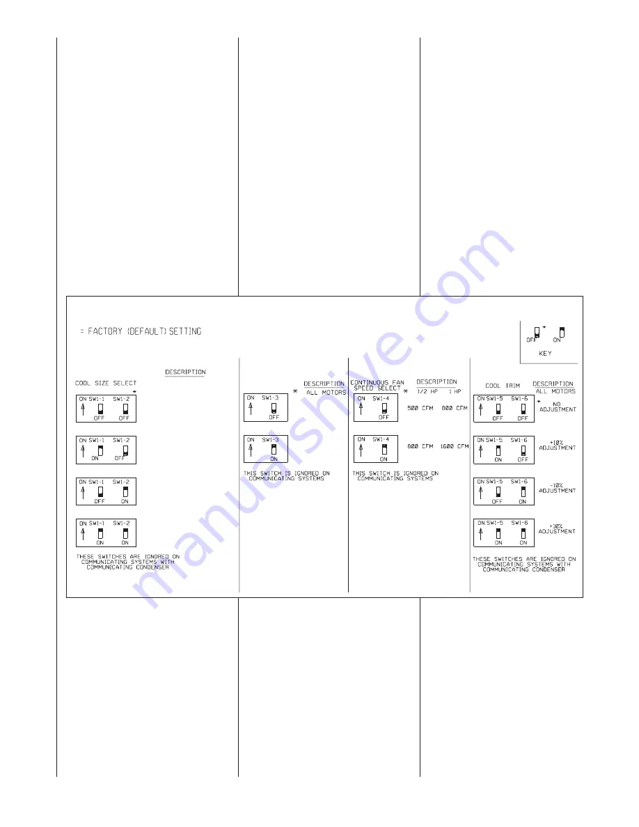
SW1-1 AND SW1-2 – COOLING AIR-
FLOW SELECT – These dipswitches
are used to select the appropriate cool-
ing airflow based on the amount
required. The switch settings do not
affect cooling airflow when installed with
a fully communicating condenser. In
that case, the condenser supplies the
information for cooling airflow which is
preset at the factory and not adjustable.
Cooling airflow for non-communicat-
ing systems can be adjusted
approxi/- 10% by using the
cool trim adjustment dipswitches;
SW1-5 and SW1-6. See Figure 34.
Cooling airflow for non-communicat-
ing systems is also affected by the
settings of dipswitch position SW2-6.
This switch will determine the appro-
priate amount of airflow to be used
for the low stage (1
st
stage) of cool-
ing. See the tables in Figure 35.
More information can be found in
the section titled SW2 (SW2-6).
Consult the tables in Figures 34, 35
and 36 for target airflow settings and
adjustments based on the positions
of the dipswitches SW1-1, SW1-2,
SW1-5, SW1-6 and SW2-6.
FIGURE 34
DIPSWITCH BANK SW1
TIMED HEAT STAGING
NORMAL
NO STAGING
TIMED
STAGING
*
(-)GPE-05(-)BMKR (-)GPE-07(-)BRQR (-)GPE-10(-)BRMR
(-)GLE-05(-)BMKR (-)GLE-07(-)BRQR (-)GLE-10(-)BRMR
(-)GPE-07(-)AMKR
(-)GPE-12(-)ARMR
(-)GLE-07(-)AMKR
(-)GLE-12(-)ARMR
1200 CFM
1600 CFM
2000 CFM
1000 CFM
1400 CFM
1600 CFM
800 CFM
1200 CFM
1400 CFM
600 CFM
1000 CFM
1200 CFM
44
Summary of Contents for RGLE series
Page 58: ...TABLE 17 NORMAL OPERATION CODES 58...
Page 66: ...TABLE 20 FURNACE FAULT CODES EXPANDED W DESCRIPTIONS AND SOLUTIONS CONTINUED 66...
Page 67: ...TABLE 20 FURNACE FAULT CODES EXPANDED W DESCRIPTIONS AND SOLUTIONS CONTINUED 67...
Page 68: ...TABLE 20 FURNACE FAULT CODES EXPANDED W DESCRIPTIONS AND SOLUTIONS CONTINUED 68...
Page 69: ...69 TABLE 20 FURNACE FAULT CODES EXPANDED W DESCRIPTIONS AND SOLUTIONS CONTINUED...
Page 70: ...TABLE 20 FURNACE FAULT CODES EXPANDED W DESCRIPTIONS AND SOLUTIONS CONTINUED 70...
Page 71: ...TABLE 20 FURNACE FAULT CODES EXPANDED W DESCRIPTIONS AND SOLUTIONS CONTINUED 71...
Page 72: ...TABLE 20 FURNACE FAULT CODES EXPANDED W DESCRIPTIONS AND SOLUTIONS CONTINUED 72...
Page 75: ...TABLE 20 FURNACE FAULT CODES EXPANDED W DESCRIPTIONS AND SOLUTIONS CONTINUED 75...
Page 76: ...TABLE 20 FURNACE FAULT CODES EXPANDED W DESCRIPTIONS AND SOLUTIONS CONTINUED 76...
Page 77: ...TABLE 20 FURNACE FAULT CODES EXPANDED W DESCRIPTIONS AND SOLUTIONS CONTINUED 77...
Page 79: ...FIGURE 46 WIRE DIAGRAM 79...
Page 95: ...95...
Page 96: ...96 CM 0810...


