6
Test #2- Blocking Diode
1.
Remove solar panel from the battery terminals.
2.
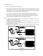
Refer to figure 3-2, Diode test #1. Using a multimeter, set the meter to read ‘Ohns’. The ‘COM”
probe must be placed on the diode as shown in Diode Test #1. Check ohms resistance across the
blocking diode. A zero or low ohms reading should be present across the diode. If not, reading a
high resistance, the diode is bad or diode is installed backwards.
3.
Refer to figure 3-2, Diode test #2. This test is similar to step #2 but the meter probes are
reversed. The ‘COM” probe must be placed on the diode as shown in Diode Test #2. Check
ohms resistance across the blocking diode. A high resistance ohms reading should be present
across the diode. If not, reading a zero or low, the diode is backwards.
Note:
•
If in Diode test #1 the resistance is zero or low and in Diode test #2 the resistance is high, then
the diode is good and installed correctly.
•
If in Diode test #1 the resistance is high and in Diode test #2 the resistance is zero or low, then
the diode is good but installed backwards.
•
If in Diode test #1 the resistance is high and in Diode test #2 the high resistance is high, then the
diode is bad and must be replaced.
•
If in Diode test #1 & Diode test #2 the resistance is zero or low, then the diode is bad or missing.
Figure 3-2


