background image

SNAP2411 

SNAPCOM UTILITY 

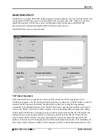
SNAPCom is a simple TCP/UDP utility program to help familiarize the user with the SNAP and 
its operation. SNAPCom can be executed off the CD or copied onto a PC. There is no need to 
install the program. SNAPCom is not a configuration utility and assumes the SNAP has 
previously been configured using WinSNAP and/or a telnet session. 
The SNAPCom screen is shown below: 


TCP Client Operation 

When the SNAP is set to operate as a client in TCP mode, select TCP and Server in the 
SNAPCom window. The PC running SNAPCom will act as the server. The IP address of the PC 
running SNAPCom must be entered into the SNAP as the server using the 

tcp server


command. In the Bind Info block of the SNAPCom screen, enter the port number to be used to 
listen to the SNAP in the Port Number window. Click on the Bind button to apply this setting.  
At this point, SNAPCom is listening for open socket requests from the SNAP. The SNAP will 
initiate an open socket request whenever a remote connects with the SNAP. When the first 
remote links with the SNAP, a message indicating the remote has linked along with the IP 
address of the remote will be displayed in the Winsock Information window. The IP address of 
the remote and the Winsock number will be displayed in the Transmit Information block of the 

©

 2000- 2004 Cirronet

 Inc 

16 

M-2411-0012 Rev - 

Summary of Contents for SNAP2411

Page 1: ...SNAP2411 X D DX Spread Spectrum Network Access Point Installation Guide ...

Page 2: ...nal radiators transmitting the same information Any other mode of operation using this antenna is forbidden Notice to users installers using the following fixed antennas with Cirronet RF products Cushcraft 15dBi Yagi Mobile Mark 14dBi Corner Reflector Mobile Mark 9dBi Corner Reflector The field strength radiated by any one of these antennas when connected to Cirronet RF products may exceed FCC man...

Page 3: ...ransceiver EN 55022 EN 55024 EN 300 328 EN 301 489 1 17 EN 60950 Canadian Department of Communications Industry Canada IC Notice Canadian Department of Communications Industry Canada IC Notice This apparatus complies with Health Canada s Safety Code 6 IC RSS 102 To prevent radio interference to the licensed service this device is intended to be operated indoors and away from windows to provide max...

Page 4: ...connecting multi conductor cable run in approved conduit for the location The cable must be in the conduit until out of the Hazardous Location and the conduit must be gas tight so no gases can flow through conduit 4 Do NOT remove the power connector to the device while circuit is live Disconnect power only while circuit is dead or the location is known to be non hazardous Failure to do so may resu...

Page 5: ...ennas 14 SNAPCom Utility 16 TCP Client Operation 16 TCP Server Operation 17 UDP Operation 18 SNAP Operation 20 Overview 20 DHCP 20 BOOTP 20 Synchronization 21 SNAP System Commands 22 Ethernet Commands 23 SNAP Radio Commands 24 Radio Commands 25 TCP IP Mode Operation 26 Client Mode 26 Server Mode 27 Assigning Remotes IP Addresses 28 Assigning Remotes Port Numbers 29 TCP IP Commands 30 UDP Mode Oper...

Page 6: ...SNAP System Commands 39 Ethernet Commands 39 SNAP Radio Commands 39 Radio Commands 40 TCP Commands 40 Appendix a 43 Specifications 45 Warranty 46 ...

Page 7: ... benefits of frequency hopping spread spectrum technology that the WIT2411s do Namely the immunity to multipath fading and resistance to jamming that is provided by changing frequency every few milliseconds Operating in the 2 4GHz ISM band SNAPs can be used license free The SNAP has three modes of operation TCP IP UDP and PPP The default mode is the TCP IP mode In TCP IP mode the SNAP acts like an...

Page 8: ...ed to the application as individual IP addresses or port numbers The default settings in the SNAP are sufficient to allow connection to Ethernet networks and to have remote WIT2411 devices connect with the SNAP Other steps you may want to take include Enter a default route IP address if data is to be sent off the SNAP s subnetwork See Ethernet Commands Change the network number See Radio Commands ...

Page 9: ...ng RF cable to connect the SNAP to the antenna Cirronet does not recommend using RF cables longer than 5 feet If more distance is required between the SNAP and the antenna Cirronet recommends using the SNAP2411X If the SNAP2411X is not used high quality low loss RF feed line must be used The 10 100BaseT Ethernet connector is the standard RJ 45 connector The connector is wired to be able to connect...

Page 10: ...sed with the existing network preventing configuration through a telnet session See the section Configuring the SNAP for details of using this port SNAP Status Indicators The PWR indicator on the front panel indicates that power is applied to the SNAP A flashing LED indicates the SNAP is executing the built in memory test TXD and RXD are indicators of data activity They indicate the transmission a...

Page 11: ...f 100 feet to 300 feet in 100 foot increments The remote radio assembly has mounting holes to secure the antenna The antenna is attached to the remote radio through the included 24 inch RF cable If the antenna is not to be mounted on the remote radio assembly connection between the remote radio and the antenna must be made with high quality low loss RF cable Cirronet recommends limiting the length...

Page 12: ...port on the hub The SYNC IN and SYNC OUT signals are provided for special applications where multiple master SNAP s are co located The synchronizing signals are RS 485 levels and may be connected using an RJ 11 connector SNAPs will automatically determine which SNAP will generate the sync signal See the section Synchronization for details The Console port is an RS 232 serial port that may be used ...

Page 13: ...fully inserted Do not pull on the conductor forcefully as that can pull the conductor out of the pin Use the following color code to insert the pins into the connector CONNECTOR PIN CONDUCTOR COLOR CONNECTOR PIN CONDUCTOR COLOR 1 Brown 9 Green 2 Orange Black 10 Orange 3 Black 11 Violet 4 Blue 12 Yellow 5 Tan 13 White Black 6 Pink 14 Grey 7 White 15 White Red 8 Red Care must be taken to follow the ...

Page 14: ...he SNAP directly to a PC without a hub the SNAP must be connected with a straight through cable Both cables are provided The synchronizing signals are provided for special applications where multiple master SNAPs are employed The synchronizing signals are RS 485 levels and may be connected using an RJ 11 connector SNAPs will automatically determine which SNAP will generate the sync signal See the ...

Page 15: ...eption of data over the Ethernet connection Note that these LEDs can be active even when the SNAP has no remote radios registered The LINK indicator when illuminated indicates a good connection to the Ethernet network If this LED is not on it can indicate a cross wired connection between the SNAP and the network It may also indicate a faulty cable connection The RF LINK LED indicates a socket conn...

Page 16: ... Remote Radio Assembly Note that the remote radio assembly should be mounted on a tower or building top oriented as in Figure 5 It is important that the RF connector on the remote radio assembly point to the ground to avoid any issues with rain water Note The SNAP2411X it must be limited to 12 26VDC 10 Failure to meet this specification can result in damage to the remote radio assembly The 10 100B...

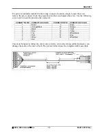
Page 17: ...vides a 12 volt power level to the SNAP The SNAP can accept DC voltages ranging between 12VDC and 26VDC if alternative power supplies are to be used Attaching the Data Power Cable Connector The figure below shows the pin numbering of the Phoenix Contact 16 pin 3 81mm Data Power connector P N1803714 The view provided is facing the side of the connector with the screw heads showing The cable comes w...

Page 18: ...he connector CONNECTOR PIN CONDUCTOR COLOR CONNECTOR PIN CONDUCTOR COLOR 1 Brown 9 Green 2 Orange Black 10 Orange 3 Black 11 Violet 4 Blue 12 Yellow 5 Tan 13 White Black 6 Pink 14 Grey 7 White 15 White Red 8 Red Care must be taken to follow the color code correctly An incorrectly assembled connector can damage the radio or the card or both The picture below shows the completed cable assembly 2000 ...

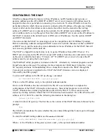
Page 19: ...AP If a DHCP server is not to be used the IP address must be set using the Console port The WinSNAP utility program is included on the CD Alternatively terminal programs such as HyperTerminal can be used The settings for the serial port are 38400 baud 8 data bits 1 stop bit no parity and none for handshaking Once connection is made to the SNAP through the Console port and power is applied to the S...

Page 20: ...after cycling power Note The save and reset commands must be entered after modifying the default configuration Failure to do so will result in the factory defaults to be used European Union Settings When operating the SNAP2411 in France a limited frequency mode must be selected To select the limited frequency band at the SNAP prompt enter hop set 1 CR Save this setting by typing save CR The limite...

Page 21: ...SNAP2411 This parameter will take effect immediately and will be saved into memory for use when power is cycled 2000 2004 Cirronet Inc 15 M 2411 0012 Rev ...

Page 22: ...ress of the PC running SNAPCom must be entered into the SNAP as the server using the tcp server command In the Bind Info block of the SNAPCom screen enter the port number to be used to listen to the SNAP in the Port Number window Click on the Bind button to apply this setting At this point SNAPCom is listening for open socket requests from the SNAP The SNAP will initiate an open socket request whe...

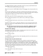
Page 23: ...ck ID TCP Server Operation When the SNAP is set to operate as a server in TCP mode select TCP and Client in the SNAPCom window The SNAPCom screen will change to reflect the client mode The PC running SNAPCom will now act as a client of the SNAP and will be responsible for initiating the open socket requests In the Connect Information block the IP address and the port number of the remote device to...

Page 24: ...tons are grayed out In order to learn what remote devices are linked to the SNAP SNAPCom must bind to the port assigned in the SNAP This port number is entered in the Port Number window in the Bind block on the SNAPCom screen The Bind button must be clicked to apply the port number setting To transmit to a specific remote enter its IP address and Port Number in the respective windows in the Tranms...

Page 25: ...SNAP2411 Received data will be displayed in the main SNAPCom window 2000 2004 Cirronet Inc 19 M 2411 0012 Rev ...

Page 26: ...te WIT2411 devices To use this mode the remote host must be capable of establishing and supporting PPP sessions UDP User Datagram Protocol is one of the protocols for data transfer that is part of the TCP IP suite of protocols UDP is a connectionless protocol because unlike TCP it does not require the sender and receiver to establish a connection before data is transmitted It s considered unreliab...

Page 27: ...ll broadcast a message over the Ethernet indicating it wants to be come a sync master responsible for generating the sync signal If no response is received to this broadcast message the SNAP will issue another broadcast message indicating it is now the sync master The sync signal will be available on the Sync Out connector on the rear of the SNAP All co located SNAPs must have the Sync connectors ...

Page 28: ...to echo characters typed by the user Default is on If echo is turned off characters typed will not be displayed on the screen unless echoed by the terminal program help Displays a list of all the SNAP commands Most commands that require a parameter also have a help mode that displays the help screen for that command reset Resets the SNAP and loads saved parameters into active memory Also causes th...

Page 29: ... a debugging tool for setting up networks ipaddr is the device IP address and eaddr is the physical Ethernet address of the device dns Sets or displays the ip addresses to be used for the primary and backup DNS servers If not set DNS name resolution must be handled by a proxy server or a DNS server ip address must be set in the subscriber PCs ip Sets the IP address of the SNAP The default IP addre...

Page 30: ...he Radio Commands detailed in the next section Command Description hop help set hoppattern Displays help screen for command Sets displays hopping pattern remote help list Displays help screen for command Displays remotes currently registered with the SNAP sync help disable enable settings Displays help screen for command Turns sync off default Turns sync on Displays synchronization settings hop Sh...

Page 31: ...network number for the SNAP Default 0 radio show Displays radio parameters that have been modified from factory settings help Displays list of sub commands under the radio command banner Displays the power on banner of the radio inside the SNAP defaults Replaces any modified parameters with the factory default values maxremotes Sets a limit to the number of remotes that an access point radio can h...

Page 32: ...and port number have been entered If no server IP address is entered into the SNAP the SNAP will default to assume the role of the server Enter the server IP address and port number by typing at the TCP prompt tcp server add ipaddr port CR where ipaddr is the IP address and port is the port number of the desired server Two server IP addresses may be entered Information on the server IP addresses i...

Page 33: ...t from the SNAP The default port number for the control port is 2430 This port number can be changed using the tcp control command tcp control 1 65 536 CR The format of the registration message is 02 67 95 192 168 0 212 5002 Where indicates the beginning of a registration message 02 67 95 is the factory serial number of the remote radio and 192 168 0 212 is the IP address and 5002 is port number t...

Page 34: ... of the pool must be equal to the maximum number of remotes that will register with the SNAP at a given time The default setting is 16 but the SNAP can support a maximum of 62 The number of remotes that can be simultaneously registered with the SNAP can be modified using the tcp server ipcount command tcp server ipcount 1 62 CR When using IP addresses to identify remote devices the SNAP will assig...

Page 35: ...d into the SNAP the remote devices will be identified by dynamically assigned port numbers of the IP address of the SNAP As remotes register with the SNAP the SNAP will dynamically and randomly assign port numbers The SNAP will not assign a remote device port numbers reserved for standard services such as FTP To make a static assignment of a port number to a specific remote device use the tcp remo...

Page 36: ... 1 65536 list Sets base IP address for SNAP Add a server IP address Delete a server IP address Enable disable connect message on remote registration Set beginning IP address for dynamic IP assignment Set number of remotes that can be connected to servers simultaneously Set port number to use when IP address used to identify remotes List servers entered tcp status Displays status of servers and rem...

Page 37: ...servers to be communicated with when the SNAP is in client mode The id command turns on a connect message whenever a remote registers with the SNAP When not enabled the SNAP will open a socket for each remote as they register but will not provide any other indication of a remote registering status Displays the status of servers and remotes 2000 2004 Cirronet Inc 31 M 2411 0012 Rev ...

Page 38: ...ontrol 1 65536 Displays control port setting for server mode Sets control port for server mode remote help add remote id portnum ipaddr delete remote id list Displays help screen for command Add a remote with a static IP address assignment Remote ID must be broken up by dashes after every two numbers Remove a static IP address assignment Displays a list of remotes with static IP addresses server h...

Page 39: ...he WIT2411 in the remote device with a dash separating each two digits For example serial number 201457 must be entered as 20 14 57 server Sets up and manages server or servers to be communicated with when the SNAP is in client mode The id command turns on a connect message whenever a remote registers with the SNAP When not enabled the SNAP will open a socket for each remote as they register but w...

Page 40: ...fy the starting IP address for the remotes that logon The first remote to logon will receive the IP address specified below The SNAP will then add one to the IP address for the next remote to login Alternatively the SNAP supports static IP assignment based on username Details of the commands for these modes are in the section PPP Commands below Included in the appendix is a listing of a Windows mo...

Page 41: ...t 1 60 Displays PPP base allocation count Set to max number of remotes parameter of radio ip usr ipaddr Sets static IP address for specified user radius help add auth acct ipaddr port delete auth acct ipaddr port auth acct ipaddr port number retries value secret auth acct ipaddr secret settings timeout value Displays help screen for command Adds IP address of Radius server for authentication or ac...

Page 42: ...one count Displays sets the PPP base allocation count This number must be equal or larger than the maximum number of remotes the radio as it determines the number of buffers the SNAP will set up to asSNAPble SNAP datagrams ip Sets static IP assignment for the designated usr where usr is the username assigned to the subscriber in the SNAP The IP assignment remains valid after cycling power to the S...

Page 43: ...ser is added a password must be assigned and the user must be enabled before access will be granted A user and password must be assigned only if local authentication is user If a Radius server is to perform authentication usernames and passwords are not required There is no way to display passwords If a password is forgotten a new password must be entered 2000 2004 Cirronet Inc 37 M 2411 0012 Rev ...

Page 44: ... can be seen through switches hubs and routers Cannot communicate with a remote radio Check the list of registered remotes on the SNAP to make sure the remote is registered using the remote list command If the remote is not registered check that the remote is not is sleep mode Verify that the remote is in range of the SNAP Technical Support Technical Support is available from Cirronet from 8 30am ...

Page 45: ...entry dns Displays current DNS server IP address ipaddr netmask Sets DNS server IP address ip ipaddr netmask Sets SNAP IP address and optional netmask ping ipaddr Pings TCP IP hosts route help add ipaddr default Adds IP address and netmask to route table gwaddr netmask del ipaddr Deletes IP address from route table list Lists route table IP addresses socks Diplays network socket information SNAP R...

Page 46: ...c IP assignment ipaddr delete remote id Remove a static IP assignment list Displays remotes with static IP assignment server help add ipaddr port Add a server IP address delete ipaddr Delete a server IP address id enable disable Enable disable remote connect message ipbase ipaddr Set beginning IP address for dynamic IP assignment ipcount 1 62 Set number of remotes that can connect to server simult...

Page 47: ...erver ipaddr port delete auth acct Deletes IP address of Radius server ipaddr retries value Sets the RADIUS number of retries port auth acct ipaddr pnumber Sets the port number for a Radius server secret auth acct ipaddr secret Sets the secret for a Radius server settings Displays Radius server settings timeout value Sets RADIUS timeout in tenths of a second status Displays status of registered us...

Page 48: ...p Duration base only pl Get Maximum Data Length pn 01 3e Set Maximum Number of Remotes base only pr 00 ff Set Packet Attempts Limit pv 0 1 Set Slot Assignment Mode base only pw 00 ff Set Base Slot Size base only Status Commands zb 0 1 Banner Display Disable zh Read Factory Serial Number High Byte zm Read Factory Serial Number Middle Byte zl Read Factory Serial Number Low Byte z Exit Modem Control ...

Page 49: ...im XofLim Xon Xof Err Eof Evt 115200 HKR DCB 1 1C 00 00 00 00 c2 01 00 15 20 00 00 00 00 0a 00 0a 00 08 00 00 11 13 00 00 00 DWC00Reg Null Modem HKR Init 1 cr cr HKR Init 2 NoResponse HKR Settings Prefix HKR Settings DialPrefix HELLO cr HKR Settings Terminator cr HKR Monitor 1 None HKR Answer 1 HELLO HKR Answer 2 NoResponse Properties dwords and words are byte reversed Dial Options InactivityTimeo...

Page 50: ...NECTED HKR Responses cr 1 02 00 00 00 00 00 00 00 00 00 Accept any recvd data as CONNECTED HKR Responses lf 1 02 00 00 00 00 00 00 00 00 00 Accept any recvd data as CONNECTED HKR Responses cr lf 1 02 00 00 00 00 00 00 00 00 00 Accept any recvd data as CONNECTED end of 23 May 98 addition Strings DWC Cirronet Incorporated Man Cirronet Incorporated ...

Page 51: ...o 70 C 30 C to 70 C 30 C to 70 C remote radio unit 40 C to 70 C Network Interface 10 100BaseT SNAP Network Topologies Point to Point or Multipoint Repeater Use Cirronet HN 2011 RF Output Power 100mW with included whip antenna 400W EIRP with gain antenna RF Modulation Frequency hopping up to 64 user selectable hopping patterns Frequency Range 2400MHz to 2483 5MHz Operating Voltage Range 9VDC to 26V...

Page 52: ...power failure No suit or action shall be brought against Seller more than twelve 12 months after the related cause of action has occurred Buyer has not relied and shall not rely on any oral representation regarding the goods sold hereunder and any oral representation shall not bind Seller and shall not be a part of any warranty THE PROVISIONS OF THE FOREGOING WARRANTY ARE IN LIEU OF ANY OTHER WARR...

Reviews: