Page 23
2. Installation
It is strongly advised that the installer reads Section 1 of this manual prior to starting any installation work. It is a
requirement that only qualified and competent personnel undertake installation, commissioning, and servicing.
WARNING
Always ensure that the appropriate personal protective equipment is used.
2.1 Packaging/siting
The heater will usually be supplied wrapped in heavy gauge polythene, non
assembled parts will be supplied separately.
Prior to installation, the assembly of the heater should be completed, it is
advisable that this is undertaken in the area where the heater is scheduled to
be sited.
CAUTION
The Heater must be installed within the mounting heights indicated
below in metres.
The following clearances in mm must be observed *when suspended:
2.2 Heater Mounting
The heater and flue must be adequately supported by one of the following methods;
•
Suspension by steel drop rods or straps from the M10 fixing points located on top of the heater. These must be of sufficient strength to safely
carry the weight of the unit and ancillary equipment. The straps may only drop vertically to eyebolts, if used; I.E.
• They must not be joined to the eyebolt at an angle to the vertical, and eyebolts, if used, should be of an approved type.
•
OUH heaters can be mounted on specifically designed cantilever wall or vertical stanchion brackets which locate directly to the four
M10
fixings on the heater casing. Alternatively OUHA or OUHC units can be mounted on cantilever type wall brackets however consideration
must be given to ensure that the bracket is large enough to support the heater whilst providing the necessary clearances.
•
In either case the installer should ensure that the wall wall fixings or other support medium is capable of supporting the weight
• On a level non-combustible surface capable of adequately supporting the weight of the unit and ancillary equipment.
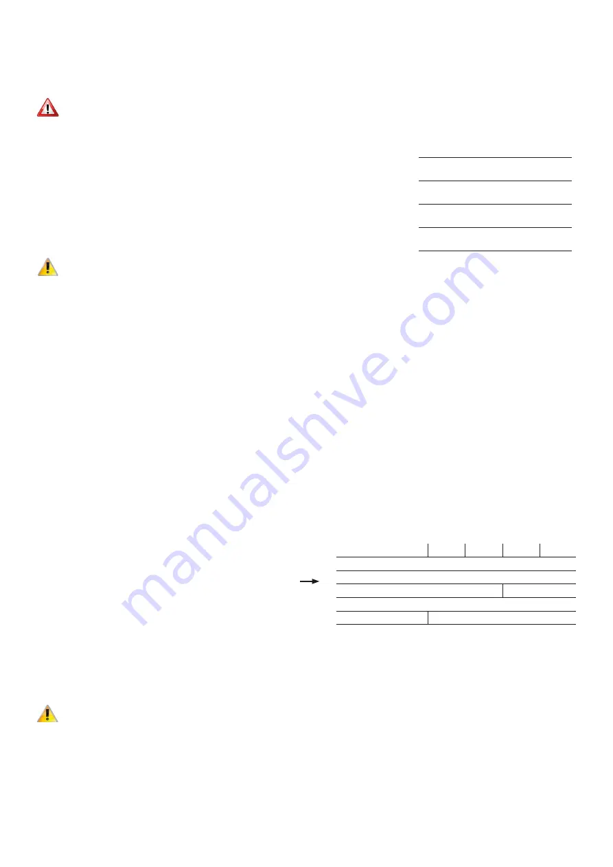
2.3 Minimum Clearances
The following minimum clearances (in millimetres) are
recommended when installing the heater.
2.4 Warm Air Circulation
The air heater should be positioned to enable maximum
circulation of discharged warm air within the area to be
heated, whilst taking account of personnel within the area,
sources of cold air ingress, and obstructions.
CAUTION
Ensure louvres are adjusted outwards and ensure blades are not resonating
The air temperature rise on passing the heat exchanger is typically around 34°C. A full and unobstructed return air
path to the air heater must be provided (see 1.11 Air Supply).
Where the heater is positioned to deliver blown air through an opening in a wall, return air intakes should be located
so that they cannot become blocked. Similarly these intakes must be positioned so as not to draw in odours, fumes,
hazardous vapours or particles.
Model
Min
Max
40
2.0
2.7
60
2.4
3.0
70
2.4
3.5
90
2.5
3.5
100
2.4
3.5
Model
40
60
70
90
100
Above
300
Below*
300
RHS
680
810
LHS
250
Rear OUHA
400
560
Rear OUHC
200
Summary of Contents for OUH 100
Page 46: ...Page 46 Notes...


