Reznor GVR 100 Installation Operation & Maintenance Download Page 46

Form I-VR (10-14), P/N 205202 R14, Page 46

Model VR/GVR 

Configuration Drawings

 ..................... Form T-VR-CNFG

Replacement 

Parts  ...........................................................Form P-VR/RIH

REFERENCES 


(Forms are available on Website 
www.ReznorHVAC.com or from 
your Distributor.)

Addendum 

(cont’d)

Model VR/GVR 

Technical Information

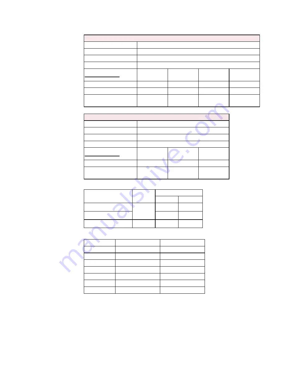
Model VR (std 60 Hertz)
Voltage/Phase

Standard 115/1; Optional 208/1, 230/1 

Frequency

60 hertz

Control Amps (24V)

0.8

Main Burner Ignition

Direct Spark

Full Load Amps 

Sizes 50, 75, 


and 100

Sizes 125 


and 150

Size 175

Size 200

115V

1.1

0.8

1.2

1.2

Optional 208V or 230V

0.5

0.5

0.6

N/A

Maximum Overcurrent 

Protection

15

15

15

15

BTUH Input

Gas Type

Supply Pressure

Minimum Maximum

50,000 - 150,000

Natural 

Gas

4.5” w.c.

14” w.c.

175,000 - 200,000

6” w.c.

14” w.c.

50,000 - 200,000

Propane

11” w.c.

14” w.c.

BTUH Input

Minimum Length

Maximum Length

50,000

20 feet (6.1M)

40 feet (12.2M)

75,000

20 feet (6.1M)

40 feet (12.2M)

100,000

30 feet (9.1M)

50 feet (15.2M)

125,000

30 feet (9.1M)

60 feet (18.3M)

150,000

40 feet (12.2M)

60 feet (18.3M)

175,000

40 feet (12.2M)

70 feet (21.3M)

200,000

50 feet (15.2M)

70 feet (21.3M)

Gas Type and Supply 

Gas Pressure

Electrical 

Characteristics

BTUH/Length/

Configurations

Model VR (optional 50 Hertz) and Model GVR (std 50 Hertz)
Voltage/Phase

220-240/1 (Option AK11)

Frequency

50 hertz

Control Amps (24V)

0.8

Main Burner Ignition

Direct Spark

Full Load Amps 

Sizes 50, 75, 


and 100

Sizes 125 


and 150

Size 175

Optional 220-240/1/50

0.5

0.5

0.6

Maximum Overcurrent 

Protection

15

15

15

Summary of Contents for GVR 100

Page 1: ...ead and understand the installation operation and service instructions in this manual Improper installation adjustment alteration service or maintenance can cause serious injury death or property dama...

Page 2: ...tion DE2 Combustion Air Inlet Kit must be used There are warning labels on the unit and throughout this manual For your safety read the definitions below and comply with all boxes labeled CAUTION WARN...

Page 3: ...M to the bottom of the heater from the highest surface of the wings or engine enclosures of the highest aircraft which may be housed in the hangar NFPA 409 and CAN CSA B149 1 specify a minimum clearan...

Page 4: ...more comfortable temperature than with convection warm air heating equipment For optimum comfort when infrared heaters are being used to heat personnel spot heating it is recommended that 1 the rays...

Page 5: ...TUH heater Conversion kit to change to a Size 100 000 BTUH heater VR 125 150 Factory assembled Size 125 000 BTUH heater Conversion kit to change to a Size 150 000 BTUH heater VR175 200 Factory assembl...

Page 6: ...ations Dimensions and Clearances FIGURE 1 Tube Cartons include Tubes Reflectors Hangers Brackets Couplings and Hardware Important NOTE Before installation wipe any excess corrosion inhibitor from the...

Page 7: ...ze and Configuration meters 50 6 1 9 1 12 2 6 1 9 1 12 2 6 1 9 1 12 2 7 6 10 7 7 6 9 1 10 7 12 2 75 6 1 9 1 12 2 6 1 9 1 12 2 6 1 9 1 12 2 7 6 10 7 7 6 9 1 10 7 12 2 100 9 1 12 2 15 2 9 1 12 2 15 2 12...

Page 8: ...tibles Size Below Top Horizontal Clearances Vent Burner End Heat Exchanger Bend U or L Exhaust End 50 75 100 inches 66 12 24 36 24 6 mm 1676 305 610 914 610 152 125 150 inches 78 12 30 48 24 6 mm 1981...

Page 9: ...ly are the responsibility of the installer Follow all instructions carefully All burner control boxes require some field preparation The type of preparation depends on how the unit was ordered and whe...

Page 10: ...Only On a Size 200 change the pressure switch Instructions for Changing Pressure Switch a In the control compartment locate the pressure switch See FIGURE 5 b Mark and disconnect the two wires attach...

Page 11: ...0 0 25 0 30 Label Color Gray Pink Green 6 2 Assemble and Suspend the Heater 6 2 1 Assemble the Burner Control Box and the Combustion Chamber Tube Use these parts from the hardware bag to assemble the...

Page 12: ...ion is going to be horizontal and a turnbuckle has been used close the S hooks If the reflector is going to be angled or there is no turn buckle leave the S hooks open until after the system is levele...

Page 13: ...raight Heat Exchanger Tube 10 ft 3M or 5 ft 1 5M Option UA1 L Heat Exchanger Tube Option UC2 U Heat Exchanger Tube Option UB3 FIGURE 13C Tube Coupling with Tighten ing Bolts and Two Self drilling Scre...

Page 14: ...elf Drilling Screws With both tube ends as far into the coupling as they will go tighten the coupling bolts In the top insert the two self drilling screws to secure the coupling to each tube Use the s...

Page 15: ...acent to the exhaust heat exchanger tube See FIGURE 17B 5 5 2 sections before U or L is connected Into end of straight tube before U or L 3 sections after exhaust heat exchanger tube is connected Into...

Page 16: ...are shipped with the tubes Clips and screws for length of system are included in the tube package hardware bag FIGURE 18 Reflector for Straight Tubes Parts Tools Needed Clips and screws from the tube...

Page 17: ...nges FIGURE 19B To allow for reflector expansion the clip must have a minimum of 1 1 4 32mm clearance from a tube bracket between the clip and the burner box Position each clip drill 1 8 hole and inse...

Page 18: ...ed to fit the installation 6 Mechanical cont d 6 2 Assemble and Suspend the Heater cont d 6 2 4 Install Reflectors and Optional Side Shield and or End Covers cont d Straight Tube Reflector Installatio...

Page 19: ...needed At that location install one of the wire reflec tor retainers and a tube bracket supplied with the side shield NOTE Sus pension is not required at any of the additional wire reflector retainer...

Page 20: ...tubes should be at right angles and U shaped systems should be parallel 6 Mechanical cont d 6 2 4 Install Reflectors and Optional Side Shield and or End Covers cont d 6 2 Assemble and Suspend the Hea...

Page 21: ...30 79 275 168 410 250 780 476 150 31 19 64 39 120 73 250 153 380 232 710 433 175 28 17 59 36 110 67 225 137 350 214 650 397 200 26 16 55 34 100 61 210 128 320 195 610 372 Note When sizing supply lines...

Page 22: ...ntaining calibration of a spring type gauge 2 Open the valve and operate the heater Measure the outlet gas pressure Adjustment to the factory preset regulator is rarely necessary Valve Outlet Pressure...

Page 23: ...for natural gas is between 4 5 and 14 w c for Sizes 50 150 and between 6 Derate is by Valve Outlet Pressure Adjustment for High Altitude Operation This adjustment can only be done after the heater is...

Page 24: ...000 150000 175000 200000 2001 4500 611 1373 45000 67500 90000 112500 135000 157500 180000 6 4 Venting and Combustion Air Venting must be in accordance with the National Fuel Gas Code NFPA 54 ANSI Z223...

Page 25: ...ertical use at least two non corrosive screws per vent pipe joint on single wall pipe or follow the pipe manufacturer s instructions for joining double wall pipe When attaching double wall pipe to sin...

Page 26: ...pipe is used in the vent terminal follow the instructions in the Addendum page 45 to attach the vent cap and to connect the double wall pipe to the single wall vent pipe NOTE For optional vent termin...

Page 27: ...ion SINGLE WALL Single wall vent run and single wall terminal end DOUBLE WALL Single wall vent run and double wall terminal end Horizontal Vent Clearance Table Structure Minimum Clearances for Vent Te...

Page 28: ...ent Terminal Air Intake Arrangements drawings are not proportional read all information SINGLE WALL Single wall vent run and single wall terminal end DOUBLE WALL Single wall vent run and double wall t...

Page 29: ...ane gas per hour input of installed heaters Exhaust openings for removing flue products shall be above the level of the heater When mechanical means is provided to supply and exhaust a positive inter...

Page 30: ...mosphere is dirt laden 3 the atmosphere contains any substance that will cause toxic gas when passed through a flame or 4 the heater is installed in a tightly closed room that does not provide require...

Page 31: ...for each opening See 1 in FIGURE 30 2 Air from outside through duct openings 1 square inch free area per 2000 BTUH See 2 in FIGURE 30 3 Air direct from outside openings 1 square inch free area per 400...

Page 32: ...115 208 230 1 60 220 240 1 50 CAPACITOR SEE NOTE 6 BR BR SPARK TRANSFORMER WIRING CODE BLACK BK BROWN BR RED R ORANGE O YELLOW Y GREEN G BLUE BL PURPLE PR WHITE W Y W1 R SET ANT AT 0 6 AMPS R W R 1C30...

Page 33: ...eater If required was the manifold pressure adjusted for high altitude Sizes 50 175 was a high altitude pressure switch installed See Paragraphs 6 1 and 6 3 If required was a size conversion kit insta...

Page 34: ...R PER 1000 BTUH S FOR NATURAL GAS OR 5 CFM OF FRESH AIR PER 1000 BTUH S FOR PROPANE 8 Check Installation and Start Up cont d With the unit operating measure manifold gas pressure See Paragraph 6 3 Tur...

Page 35: ...ch completed heating cycle Carefully inspect the flexible gas con nector for any evidence that a fatigue crack has developed or is developing If the inspection indicates that replacement is needed rep...

Page 36: ...e main burner This buildup of dirt will eventually affect the operation of the heater To maintain safe and reliable heater operation an annual cleaning more frequently in dirty environments is recomme...

Page 37: ...and inside the concentric port rings on the main burner could cause fuel gas to spill out of the back of the burner tube Fuel gas spilling out of the back of the burner tube will cause gas odor inside...

Page 38: ...1 Turn off or disconnect the main electric supply 2 Open the control access panel Rotate the knob on the gas valve to the OFF position At the ignition controller disconnect the high voltage spark elec...

Page 39: ...10 1 Control Location Operation and Service WARNING Service work on this heater should only be done by a qualified gas service person This service information and the troubleshooting guides are intend...

Page 40: ...negative building pressure When negative building pressure exists install an outside combustion air inlet An obstruction in the vent pipe or combustion air inlet Remove obstruction A dirty combustion...

Page 41: ...r FIGURE 43 Transformer Function The function of the transformer is to reduce the supply voltage to a 24 volt circuit in order to operate the 24 volt controls Transformer Check requires a voltmeter To...

Page 42: ...ine 2 Bleed gas line initial startup only 3 Gas pressure too high or too low 3 See Gas Supply Pressure Table Paragraph 6 3 4 No Spark 4 a Loose wire connections a Be certain all wire connections are s...

Page 43: ...ions 2 Defective DSI control board 2 Replace board 3 Defective motor 3 Replace motor Blower motor turns on and off while burner is operating 1 Motor overload device cycling on and off 1 Check motor lo...

Page 44: ...PEN FIGURE 46 Pressure Switch Troubleshooting Guide Is the gas supply turned on Is the gas supply pressure correct Refer to Paragraph 6 3 Is the main electrical supply on Is the correct voltage being...

Page 45: ...E 48 STEP 1 Place a continual 3 8 bead of silicone sealant around the circumference of the vent cap col lar This will prevent any water inside the vent cap from running down the double wall pipe Do ST...

Page 46: ...ressure Minimum Maximum 50 000 150 000 Natural Gas 4 5 w c 14 w c 175 000 200 000 6 w c 14 w c 50 000 200 000 Propane 11 w c 14 w c BTUH Input Minimum Length Maximum Length 50 000 20 feet 6 1M 40 feet...

Page 47: ...at Connections 32 Transformer 39 41 Troubleshooting 42 Troubleshooting Guide 44 Tube Bracket 12 13 Tube Coupling 13 Tube Packages 6 Turbulator Requirements 15 Turbulator Strip 13 14 Turbulator Strip S...

Page 48: ...____________________________ ________________________________________________________ Phone _________________________________ Model No ______________ Serial No _____________________Date of Installatio...

Reviews: