R91130613
8
Edition
0
2
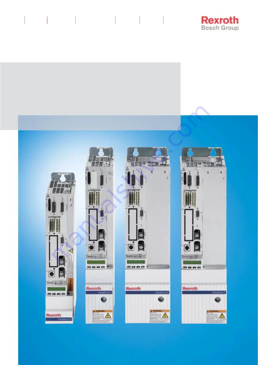
Rexroth IndraDrive C
Drive Controllers
Power Sections
HCS02.1
Project Planning Manual
IndustrialHydraulics
Electric Drivesand Controls
Linear Motion andAssembly Technologies
Pneumatics
ServiceAutomation
MobileHydraulics
Page 1: ...exroth IndraDrive C Drive Controllers Power Sections HCS02 1 Project Planning Manual Industrial Hydraulics Electric Drives and Controls Linear Motion and Assembly Technologies Pneumatics Service Autom...
Page 2: ...en Offenders are liable for the payment of damages All rights are reserved in the event of the grant of a patent or the registration of a utility model or design DIN 34 1 The specified data only serve...
Page 3: ...1 Introduction 2 1 Areas of Use and Application 2 2 2 2 Inappropriate Use 2 2 3 Safety Instructions for Electric Drives and Controls 3 1 3 1 Introduction 3 1 3 2 Explanations 3 1 3 3 Hazards by Improp...
Page 4: ...Power Section Braking Resistor 6 9 6 5 Power Section Inverter 6 10 6 6 Power Section Examples of Allowed Load Profiles 6 11 6 7 Power Section Cooling Power Dissipation Insulation Resistance Sound Pre...
Page 5: ...8 1 Products 8 1 Packaging Materials 8 1 8 2 Environmental Protection 8 1 No Release of Hazardous Substances 8 1 Materials Contained in the Products 8 1 Recycling 8 2 9 Service Support 9 1 9 1 Helpdes...
Page 6: ...IV Contents Rexroth IndraDrive C DOK INDRV HCS02 1 PR02 EN P...
Page 7: ...Project Planning Manual Rexroth IndraDrive Drive System DOK INDRV SYSTEM PRxx EN P part no R911309636 This Project Planning Manual among other things contains specifications for the components of the...
Page 8: ...CABLE STAND AUxx EN P Safety Instructions for Electrical Drives Safety Guidelines DOK GENERAL DRIVE SVSx MS P Rexroth IndraDrive Additional Components Project Planning Manual DOK INDRV ADDCOMP PRxx EN...
Page 9: ...ts of two essential parts Power section Control section Power Section The following are connected to the power section mains motor with optional motor holding brake and motor temperature monitoring 24...
Page 10: ...rained person The contacts X31 1 and X31 2 are connected to the control section as Bb contacts Note The control sections are described in a separate documentation see page 1 2 1 3 Drive Controllers Bl...
Page 11: ...imit CZW RSoftstart RB hcs_block_12v FH7 A1 A2 A3 L1 L2 L3 optional integrated control voltage supply Fig 1 4 HCS02 1E W0012 NNNV Block diagram HCS02 1E W0028 NNNN line input with bridge circuit recti...
Page 12: ...28v FH7 A1 A2 A3 L1 L2 L3 L L DC bus connection optional integrated control voltage supply Fig 1 6 HCS02 1E W0028 NNNV Block diagram HCS02 1E W0054 70 NNNN line input with bridge circuit rectifier DC...
Page 13: ...ifier DC bus capacitance converter bridge circuit with output to the motor braking resistor circuit charging current limit hcs_block_54_70v FH7 CZW A1 A2 A3 L1 L2 L3 L L DC bus connection optional int...
Page 14: ...stored or dispatched in conductive packaging Note Rexroth connection diagrams are only to be used for producing installation connection diagrams The machine manufacturer s installation connection dia...
Page 15: ...e guarantee and the right to payment of damages resulting from inappropriate use are forfeited The user alone carries all responsibility of the risks Before using Rexroth products make sure that all t...
Page 16: ...o ensure an application specific use the drive controllers are available with differing drive power and different interfaces Typical applications of drive controllers are handling and mounting systems...
Page 17: ...rson or persons responsible for the safe operation of this equipment If the equipment is resold rented or transferred or passed on to others then these safety instructions must be delivered with the e...
Page 18: ...s WARNING High electrical voltage due to wrong connections Danger to life or bodily harm by electric shock WARNING Health hazard for persons with heart pacemakers metal implants and hearing aids in pr...
Page 19: ...and accessories approved by the manufacturer Follow all safety regulations and requirements for the specific application as practiced in the country of use The equipment is designed for installation...
Page 20: ...structions for installation in accordance with EMC requirements can be found in the documentation EMC in Drive and Control Systems The machine or installation manufacturer is responsible for complianc...
Page 21: ...ven for brief measurements or tests if the ground wire is not permanently connected to the points of the components provided for this purpose Before working with electrical parts with voltage higher t...
Page 22: ...ot be smaller than the cross section of a phase of the mains supply wire Prior to startups even for brief tests always connect the protective conductor or connect with ground wire Otherwise high volta...
Page 23: ...ponents software or firmware errors Dangerous movements can occur immediately after equipment is switched on or even after an unspecified time of trouble free operation The monitoring in the drive com...
Page 24: ...sist maximum possible momentum especially if there is a possibility of loose parts flying off Mount the emergency stop switch in the immediate reach of the operator Verify that the emergency stop work...
Page 25: ...ying conductors and permanent magnets in motors represent a serious health hazard to persons with heart pacemakers metal implants and hearing aids WARNING Health hazard for persons with heart pacemake...
Page 26: ...unting Under certain conditions incorrect handling and mounting of parts and components may cause injuries CAUTION Risk of injury by incorrect handling Bodily harm caused by crushing shearing cutting...
Page 27: ...s corresponding to the information in the respective Project Planning Manual must be provided with pressurized media such as compressed air hydraulic oil cooling fluid and cooling lubricant supplied b...
Page 28: ...3 12 Safety Instructions for Electric Drives and Controls Rexroth IndraDrive C DOK INDRV HCS02 1 PR02 EN P Notes...
Page 29: ...de 5 1 Air internal through integrated blower W 6 Maximum current 6 1 12 A 0012 6 2 28 A 0028 6 3 54 A 0054 6 4 70 A 0070 7 Protection mode 7 1 IP 20 A 8 Mains connecting voltage 8 1 AC 200 to 500V 10...
Page 30: ...te Fig 4 2 Type plate arrangement Type Plate Power Section Example SN HCS021 00123 HCS02 1E W0012 A 03 NNNN R911298371 FD 04W12 0A01 Made in Germany Example 04W12 means year 2004 week 12 Production we...
Page 31: ...PR02 EN P 4 3 Scope of Delivery as standard optional Power section Control section Touch guard Accessories HAS02 1 Connectors X3 X5 X6 X13 Further accessories Connector X9 HCS02 1E W0054 and HCS02 1E...
Page 32: ...4 4 Identification Rexroth IndraDrive C DOK INDRV HCS02 1 PR02 EN P Notes...
Page 33: ...NDRV HCS02 1 PR02 EN P 5 Mechanical Data 5 1 Dimensions HCS02 1E W0012 A minimum mounting clearance when using accessories HAS02 1 plus space for cables B minimum mounting clearance plus space for cab...
Page 34: ...draDrive C DOK INDRV HCS02 1 PR02 EN P HCS02 1E W0028 A minimum mounting clearance when using accessories HAS02 1 plus space for cables B minimum mounting clearance plus space for cables Fig 5 2 Dimen...
Page 35: ...V HCS02 1 PR02 EN P HCS02 1E W0054 and HCS02 1E W0070 A minimum mounting clearance when using accessories HAS02 1 plus space for cables B minimum mounting clearance plus space for cables Fig 5 3 Dimen...
Page 36: ...ontroller Weight kg HCS02 1E W0012 2 9 HCS02 1E W0028 3 8 HCS02 1E W0054 6 7 HCS02 1E W0070 6 8 Fig 5 4 Weight of drive controllers without control section and accessories The weight of devices with i...
Page 37: ...fails CAUTION Risk of damage caused by too high outlet temperatures When mounting and installing other components make sure the distance to the top of the drive controllers is sufficient You have to...
Page 38: ...the device to air outlet at the top of the device depending on the average continuous power at the breaking resistor The values d are representing different distances from the top of the device see f...
Page 39: ...d 80mm T d 120mm PBD average continuous power of braking resistor d distance from the top of the device Fig 5 7 HCS02 1E W0012 HCS02 1E W0028 0 10 20 30 40 50 60 70 80 90 100 0 15 30 45 60 75 90 105...
Page 40: ...d 40mm T d 80mm T d 120mm PBD average continuous power of braking resistor d distance from the top of the device Fig 5 9 HCS02 1E W0054 HCS02 1E W0070 0 20 40 60 80 100 120 0 50 100 150 200 250 300 3...
Page 41: ...le phase cos 1 L 0 4 0 4 0 4 0 4 total power factor TPF at PDC without with mains choke cos 1 L 0 6 0 6 0 7 0 64 0 75 0 56 0 76 power factor of fundamental component DPF PDC without with mains choke c...
Page 42: ...kWs 1 5 9 13 storable energy of the internal DC bus capacitors at 3AC400V WDC Ws 19 38 57 95 lower DC bus voltage limit UDC limit min V 200 see also Functional Description of firmware upper DC bus vo...
Page 43: ...base_1 kW 1 5 1 5 4 7 4 2 6 2 9 1 8 3 13 3 DC bus peak power UN1 3 x AC 400 V at Ta 40 C t 2 s T 20 s without mains choke with mains choke PDC_peak_3 kW 5 5 8 10 12 16 14 19 DC bus power UN1 3 x AC 40...
Page 44: ...AC 400 V at Ta 40 C t 60 s T 10 min without mains choke with mains choke PDC_base_5 kW 1 5 1 5 4 7 4 2 6 2 9 1 8 3 13 3 Abb 6 3 Data power section DC bus power CAUTION Damage due to drive controller o...
Page 45: ...tinuous power over the mains connection voltage range Using HNL mains chokes increases the allowed DC bus continuous power for W0054 and W0070 devices because this reduces the load of the DC bus capac...
Page 46: ...to the diagrams below are allowed Note Single phase mains connection via the connections L1 and L2 is only allowed for single source supply Apart from the specified continuous power there is no peak p...
Page 47: ...elation between mains connection power SLN and DC bus continuous power PDCcont with and without the use of mains chokes HCS02 1 E W0012 3AC400V 0 0 5 1 1 5 2 2 5 3 3 5 4 4 5 0 0 5 1 1 5 2 2 5 PDC cont...
Page 48: ...6 8 10 12 14 16 0 1 0 2 0 3 0 4 0 5 0 6 0 7 0 8 0 9 0 10 PDC cont kW without choke with choke SLN kVA Fig 6 8 HCS02 1E W0054 HCS02 1 E W0070 3AC400V 0 2 4 6 8 10 12 14 16 18 20 0 1 0 2 0 3 0 4 0 5 0...
Page 49: ...s ON 25s OFF braking resistor continuous power at Ta 40 C under max temperature range with distance from top side of housing 1 PBD T d KW K mm 0 05 12 80 0 15 40 80 0 35 40 80 0 5 50 80 balancing fact...
Page 50: ...tput current Iout_max 4 kHz Iout_max 8 kHz Iout_max 12 kHz Iout_max 16 kHz Aeff 11 5 11 5 11 5 11 5 28 3 28 3 28 3 28 3 54 54 54 54 70 8 70 8 70 8 70 8 continuous output current effective value or rat...
Page 51: ...12 kHz Iout_base_1 16 kHz Aeff 2 6 2 4 1 5 1 1 6 3 4 1 2 3 2 0 12 0 8 8 5 8 4 8 15 3 9 4 6 3 4 7 maximum output current t 2s T 20s K 2 5 Iout_peak_3 4 kHz Iout_peak_3 8 kHz Iout_peak_3 12 kHz Iout_pea...
Page 52: ...es inverter Note The load profiles are characterized by their time flow and the corresponding currents and are representing the output current capacity These profiles are limited by the drive controll...
Page 53: ...approx 24 approx 24 approx 40 approx 40 cooling air flow together for braking resistor and power section max device power dissipation with inverter chopper and rectifier losses without internal contin...
Page 54: ...of the power sections illustrated in the following diagrams is composed of the losses of the mains supply rectifier the switching losses of the inverter HCS02 1E W0012 y axis Power dissipation W x axi...
Page 55: ...0 Pv vs Iout for HCS02 1 W0028 130 0 P V4kHz i out_4kHz P V8kHz i out_8kHz P V10kHz i out_10kHz P V12kHz i out_12kHz P V16kHz i out_16kHz 12 0 i out_4kHz i out_8kHz i out_10kHz i out_12kHz i out_16kHz...
Page 56: ...270 300 Pv vs Iout for HCS02 1 W0054 300 0 P V4kHz i out_4kHz P V8kHz i out_8kHz P V10kHz i out_10kHz P V12kHz i out_12kHz P V16kHz i out_16kHz 24 0 i out_4kHz i out_8kHz i out_10kHz i out_12kHz i out...
Page 57: ...270 300 Pv vs Iout for HCS02 1 W0070 300 0 P V4kHz i out_4kHz P V8kHz i out_8kHz P V10kHz i out_10kHz P V12kHz i out_12kHz P V16kHz i out_16kHz 36 0 i out_4kHz i out_8kHz i out_10kHz i out_12kHz i ou...
Page 58: ...N3 A 2 8 plus charging current of control section see Project Panning Manual IndraDrive Control Sections max pulse duration of IEIN3 tEIN3Lade ms 15 max input capacity CN3 mF 1 2 0 47 power consumptio...
Page 59: ...n see Project Planning Manual IndraDrive Control Sections max pulse duration of IEIN3 tEIN3Lade ms 15 max input capacity CN3 mF 1 2 0 47 power consumption HCS02 1E W0012 PN3 W 12 HCS02 1E W0028 PN3 W...
Page 60: ...ion from the DC bus 24 V hcs_block_steuerspg fh7 Br LT ST int SMPS optional ZK Br brake circuit LT power section ST control section int SMPS internal switching mode power supply ZK DC bus Fig 6 20 Blo...
Page 61: ...oltage X13 1 0V X13 2 0V X13 3 24V X13 4 24V DC bus L L L L mains connection L1 X3 L1 L2 L2 L3 L3 motor connection A1 X5 A1 A2 A2 A3 A3 motor temperature monitoring motor holding brake MotTemp X6 1 Mo...
Page 62: ...on for signaling the readiness for operation of the drive controller see Project Planning Manual for Control Section Connections at HCS02 1E W0012 Front hcs0012_front fh7 1 2 3 4 XS1 X13 Fig 6 22 HCS0...
Page 63: ...28_x3_x5_x6 fh7 X6 X3 X5 1 2 3 4 XS2 Fig 6 23 HCS02 1E W0012 power section connections bottom Description of connections Connection Page X3 Mains connection 6 28 X5 Motor connection 6 30 X6 Motor temp...
Page 64: ...054 W0070 Front hcs0028_front fh7 1 2 3 4 X1 in X1 out L L X13 XS1 Fig 6 24 HCS02 1E W0028 W0054 W0070 power section connections front Description of connections Connection Page X1 Module bus 6 27 X13...
Page 65: ...28 hcs0028_x3_x5_x6 fh7 X6 X3 X5 1 2 3 4 XS2 Fig 6 25 HC02 1E W0028 power section connections bottom Description of connections Connection Page X3 Mains connection 6 28 X5 Motor connection 6 30 X6 Mot...
Page 66: ...x9 fh7 X6 X3 X5 X9 1 2 3 4 XS2 Fig 6 26 HC02 1E W0054 W0070 power section connections bottom Description of connections Connection Page X3 Mains connection 6 28 X5 Motor connection 6 30 X6 Motor tempe...
Page 67: ...dule Bus The module bus permits data exchange between the drive controllers X1f2 FH7 X1 out X1 in Fig 6 27 X1 Type Number of poles Type of design Flat line connector 8 Connector on device Flat line bu...
Page 68: ...ual connections Identification Significance L1 phase 1 L2 phase 2 L3 phase 3 equipment grounding conductor Fig 6 30 Identification of the individual connections Note Only with single phase operation c...
Page 69: ...ded within the control cabinet or you can use the optionally available connection accessory HAS02 1 Note Observe the following for use within the scope of C UL Use 60 75 C copper wire only Use Class 1...
Page 70: ...vidual connections Identification Significance A1 phase 1 A2 phase 2 A3 phase 3 equipment grounding conductor Fig 6 34 Identification of the individual connections The outputs A1 A2 A3 are short circu...
Page 71: ...CAUTION Damage to the drive controller Strain relief cannot be provided for the motor power cable at the drive controller Strain relief for the motor power cable must therefore be provided within the...
Page 72: ...or Type Number of poles Type of design Spring power 4 Pins on device Fig 6 37 Design Identification of the individual connections Identification Significance 1 MotTemp 2 MotTemp Monitoring the motor t...
Page 73: ...ture monitor and holding brake connection CAUTION Maximum permitted braking current HCS02 1N W0012 2 0 Aeff HCS02 1N W0028 2 0 Aeff HCS02 1N W0054 2 0 Aeff HCS02 1N W0070 2 0 Aeff Where braking curren...
Page 74: ...locked off with protective fences or grids Secure vertical axes against falling or slipping after switching off the motor power by for example mechanically locking the vertical axis providing external...
Page 75: ...dentification of the individual connections HCS02 1E Cross section single wire mm Cross section multi wire mm Cross section in AWG W0054 0 5 10 0 5 10 20 8 W0070 0 5 10 0 5 10 20 8 Fig 6 43 Connection...
Page 76: ...te Technical data see page 6 18 Falling short of the permissible control voltage leads to a corresponding error message refer also to firmware function description Interruption to the control voltage...
Page 77: ...he power supply up to max 6 Aeff allowed polarity reversal protection over the allowed voltage range by internal protective diode of 24V circuit Fig 6 49 Load capacity Note The input 0 V connected in...
Page 78: ...ata Rexroth IndraDrive C DOK INDRV HCS02 1 PR02 EN P The control voltage supply is routed to the connection X13 from above see following figure 1 lines to control voltage supply Fig 6 51 Control volta...
Page 79: ...ial cases it is not possible to use the DC bus rails provided to make the connection the connection must be made using the shortest possible twisted cables Length of the twisted cables max 2 m Wire cr...
Page 80: ...nnection of Housing The ground connection of the housing is used to provide functional safety of the drive controllers and protection against contact in conjunction with the equipment grounding conduc...
Page 81: ...6 52 Shield connection XS1 Connection for shields of wires connected to the control section Note Always connect shield of cables with a large metal to metal contact surface to the shield connection C...
Page 82: ...N P XS2 Shield Connection Motor Cable XS2 hcs0028_XS2 fh7 hcs0054_XS2 fh7 XS2 Fig 6 53 XS2 XS2 is used for mounting the accessory HAS02 1 for shield connection of the motor cable See Project Planning...
Page 83: ...50 V You have to provide the best possible protection against contact Therefore keep the cutouts at the touch guard as small as possible Only break off the cutouts if necessary If the DC bus and the c...
Page 84: ...7 2 Mounting hcs_beruehrschutz fh7 Fig 7 2 Touch guard The touch guard must always be mounted following connection work Note Risk of damage to the touch guard The maximum tightening torque for the fix...
Page 85: ...tra e 2 D 97816 Lohr am Main Packaging Materials The packaging materials consist of cardboard wood and polystyrene They can be easily recycled For ecological reasons you should not return the empty pa...
Page 86: ...components can be recycled In order to recycle the metal in the best possible way it is necessary to disassemble the products into individual modules The metals contained in the electric and electron...
Page 87: ...n Sie bitte zuerst Kontakt mit unserem f r Sie n chstgelegenen Ansprechpartner auf Die Angaben in der vorliegenden Dokumentation k nnen seit Drucklegung berholt sein At www boschrexroth com you may fi...
Page 88: ...hr from 7 am 6 pm Tel 49 0 9352 40 42 22 Vertriebsgebiet S d Germany South Bosch Rexroth AG Landshuter Allee 8 10 80637 M nchen Tel 49 0 89 127 14 0 Fax 49 0 89 127 14 490 Vertriebsgebiet West Germany...
Page 89: ...11 224 88 30 Italy Italien Bosch Rexroth S p A Via Mascia 1 80053 Castellamare di Stabia NA Tel 39 081 8 71 57 00 Fax 39 081 8 71 68 85 Italy Italien Bosch Rexroth S p A Via del Progresso 16 Zona Ind...
Page 90: ...rabia no 250 sector 3 73429 Bucuresti Tel Fax 40 0 21 255 35 07 40 0 21 255 77 13 Fax 40 0 21 725 61 21 eastel rdsnet ro Romania Rum nien Bosch Rexroth Sp zo o Str Drobety nr 4 10 app 14 70258 Bucures...
Page 91: ...strial Compound Narol Naka Makwana Road Andheri East Mumbai 400 059 Tel 91 22 28 56 32 90 91 22 28 56 33 18 Fax 91 22 28 56 32 93 singh op boschrexroth co in India Indien Bosch Rexroth India Ltd S 10...
Page 92: ...511 michael moro boschrexroth ca Canada West Kanada West Bosch Rexroth Canada Corporation 5345 Goring St Burnaby British Columbia Canada V7J 1R1 Tel 1 604 205 5777 Fax 1 604 205 6944 Hotline 1 604 205...
Page 93: ...monitoring 6 32 Connection point of equipment grounding conductor 6 40 Control section 1 4 type plate 4 2 Control voltage connection 6 36 data 6 18 Control wires shield connection 6 41 D Data electri...
Page 94: ...cal data 5 1 Module bus 6 27 Motor cables 6 31 connection 6 30 holding brake 6 32 temperature monitoring 6 32 Motor cable shield connection 6 42 Motor holding brake 6 32 Motor temperature monitoring 6...
Page 95: ...6 1 mechanical 5 1 Temperatures above top of device 5 5 Touch guard 7 1 Type code HCS02 1 4 1 Type plates 4 2 U Use directions for use 2 1 hazards by improper use 3 2 inappropriate 2 2 W Warning symb...
Page 96: ...10 4 Index Rexroth IndraDrive C DOK INDRV HCS02 1 PR02 EN P...
Page 97: ......
Page 98: ...2 EN P R911306138 Bosch Rexroth AG Electric Drives and Controls Postfach 13 57 97803 Lohr Deutschland Bgm Dr Nebel Str 2 97816 Lohr Deutschland Tel 49 0 93 52 40 50 60 Fax 49 0 93 52 40 49 41 service...