background image

Falk

®

 Ultramite

®

 • Installation & Maintenance Instructions


Type UJ • Sizes 302 thru 312 

(Page 9 of 15)

rexnord.com 


GR3-016

866-REXNORD/866-739-6673 (Within the U.S.) 

08/20 (Supersedes 01/18)

414-643-2366 (Outside the U.S.) 

© Rexnord Corporation. All Rights Reserved.

SHAFT CONNECTIONS

WARNING: 

Provide suitable guards in accordance with OSHA 

standards.

Input and output shaft extension diameter tolerance is  
+.0000"; -.0005" for shafts up to 1.750" diameter and  
+.0000"; -.0010" for shafts larger than 1.750" diameter.  
The fitted component must be machined to ensure proper fit. DO 
NOT drive coupling hub, pinion, sprocket or pulley on the shaft. 
An endwise blow on the shaft may damage gears and bearings. 
Coupling hubs, pinions, sprockets or pulleys must be pushed onto 
the shaft using a screw jack device fitted into the threaded hole 
provided in the end of the shaft, see Table 1 below. 

Table 10 — Shaft End Threaded Holes – Inches

DRIVE SIZE

Input Shaft

Output Shaft

302

0.375-16 UNC-2B

0.375-16 UNC-2B

304

0.375-16 UNC-2B

0.375-16 UNC-2B

307

0.375-16 UNC-2B

0.625-11 UNC-2B

308

0.500-13 UNC-2B

0.750-10 UNC-2B

309

0.500-13 UNC-2B

0.750-10 UNC-2B

310

0.750-10 UNC-2B

0.750-10 UNC-2B

312

0.750-10 UNC-2B

1.000-8 UNC-2B

COUPLING CONNECTIONS — 

The performance and life of any 

coupling depends largely upon how well the coupling is installed 
and serviced. Refer to the coupling manufacturer’s manual for 
specific instructions.

– CAUTION – 
DO NOT HAMMER

CORRECT METHOD

Heat interference fitted coupling hubs, 
pinions, sprockets or pulleys to a 
maximum of 275°F (135°C) and slide 
onto gear drive shaft.

INCORRECT METHOD

DO NOT drive coupling hub, pinion, 
sprocket or pulley onto the shaft. An 
endwise blow on the shaft/coupling may 
damage gears and bearings.


FALK COUPLINGS — 

Detailed installation manuals are available 

from the Factory, your local Rexnord Representative or Distributor; 
just provide size and type designations stamped on the coupling. 
For lubricant requirements and a list of typical lubricants meeting 
Rexnord specifications, refer to appropriate coupling service manual.

GAP AND ANGULAR 
ALIGNMENT — 

If possible, after 

mounting coupling hubs, position 
the driving and driven equipment 
so that the distance between 
shaft ends is equal to the 
coupling gap. Align the shafts by 
placing a spacer block, equal in 
thickness to required gap, 
between hub faces, as shown, and also at 90° intervals around the 
hub. Check with feelers.

OFFSET ALIGNMENT — 

Align 

driving and driven shafts so that a 
straight edge will rest squarely on 
both coupling hubs as shown to 
the right and also at 90° intervals. 
Tighten foundation bolts of the 
connected equipment and recheck 
alignment and gap.

SPROCKETS, PULLEYS OR 
SHEAVES — 

Mount power take-offs  

as close to the gear drive housing as  
possible to avoid undue bearing load  
and shaft deflection.
Align the output shaft of the gear drive  
square and parallel with the driven 
shaft by placing a straightedge across 
the face of the sprockets or sheaves 
as illustrated.
Check horizontal shaft alignment by placing one leg of a square 
against the face of the sheave or sprocket with the spirit level on 
the horizontal leg of the square.

DO NOT overtighten belts or chains. Adjust chains to 
manufacturer’s specifications. Adjust belts as follows:
The ideal tension is the lowest tension at which the belt will not 
slip under peak load conditions. Check the belt tension frequently 
during the first 24 to 48 hours of run-in operation. Overtightening 
belts shortens belt and bearing life. Keep belts free from 
foreign material which may cause slippage. Inspect the V-belts 
periodically; tighten the belts if they are slipping.

PINION MOUNTING — 

Mount pinion as close to the drive as 

possible to avoid undue bearing load and shaft deflection. Refer to 
the Factory for pinion alignment instructions.

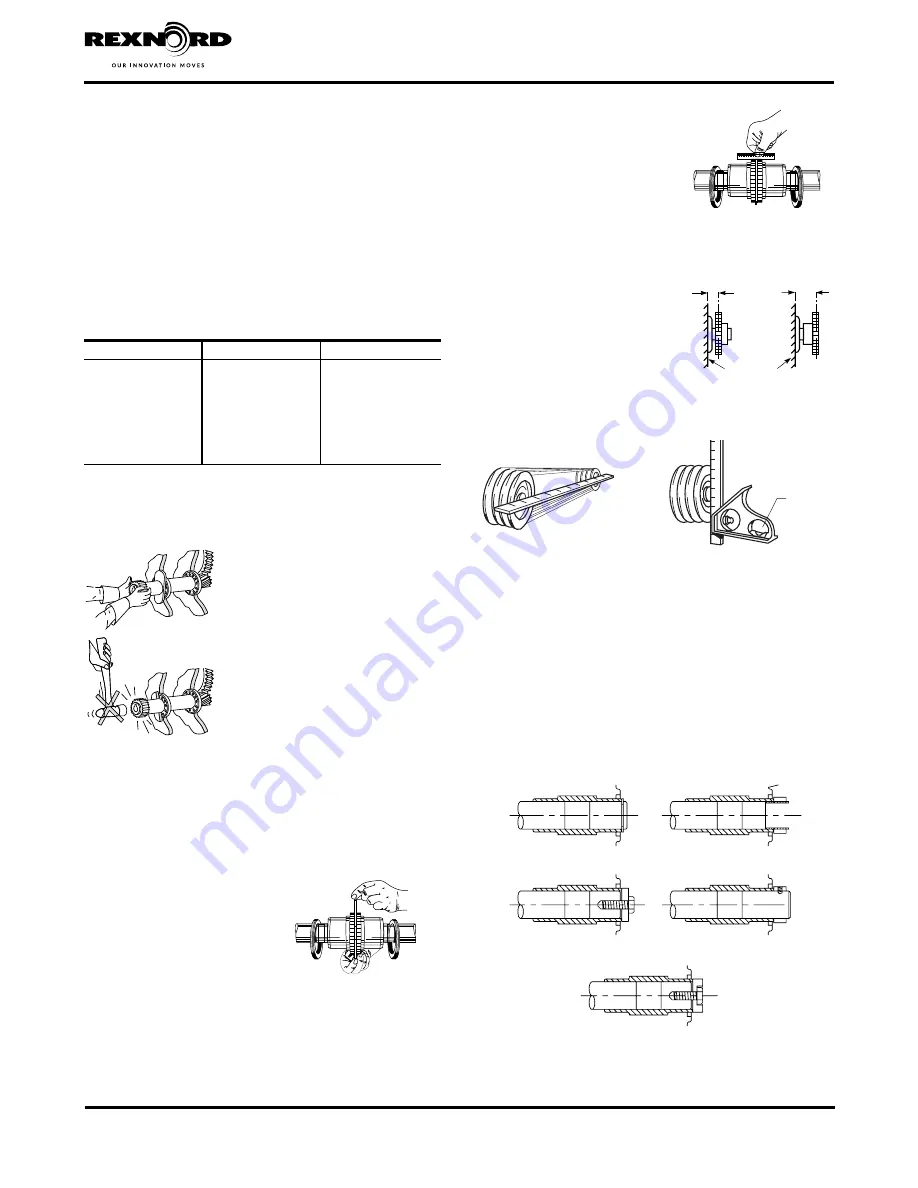
Refer to Figure 12 for methods of retaining shaft mounted drives.

DRIVE RETAINED WITH 
RETAINING RING

DRIVE RETAINED 
WITH LOCKNUT

DRIVE RETAINED WITH 
PLATE AND FASTENER

DRIVE RETAINED WITH 
COLLAR AND SETSCREW

DRIVE RETAINED WITH RECESSED PLATE AND FASTENER

Figure 12

STEELFLEX

®

 ILLUSTRATED

STEELFLEX ILLUSTRATED

LEVEL

SQUARE AND 
PARALLEL

RIGHT

WRONG

GEAR DRIVE WALL

Summary of Contents for Falk Ultramite UJ 302

Page 1: ... defined and accepted in writing by Company as a condition of operation II failure to provide suitable installation environment III use for purposes other than those for which designed or other abuse or misuse IV unauthorized attachments modifications or disassembly or V mishandling during shipping General Information The following instructions apply to standard Falk Type UJ drives shown above If ...

Page 2: ...ic housing high speed motor adapter and electric motor use Loctite 7070 Super Clean or equivalent Check for and remove any burrs from mating surfaces 4 If unit size is 308UJ or larger fill basic housing with lube type as specified in Table 13 Page 11 to the oil level plug Refer to Table 11 Page 10 for the approximate quantities of oil by the drive mounting shaft 5 Apply anti fretting compound Dow ...

Page 3: ... backing bolt nut and flat washer required Table 2 Removal Backing Bolt Data Solid Shaft DRIVE SIZE Removal Bolt Size Minimum Length Inches Maximum Tightening Torque lb ft Nm Backing Bolt Size Maximum Length Inches 302 375 16 UNC x 1 00 37 50 375 16 UNC x 1 25 304 375 16 UNC x 1 00 37 50 375 16 UNC x 1 25 306 625 11 UNC x 1 50 183 248 625 11 UNC x 1 75 307 750 10 UNC x 1 75 330 448 750 10 UNC x 2 ...

Page 4: ...TI SEIZE OR LUBRICATING COMPOUNDS 5 Tighten nut as instructed in one of the following methods PREFERRED METHOD Using a spanner Table 4 chain or pipe wrench tighten bushing nut to the torque value specified in Table 4 Note For applications where external vibratory or transient loads may act on drive and cause setscrews to become loose apply Loctite 243 or equivalent to threads of setscrew Tighten s...

Page 5: ...orrosive environments consideration should be given to use of an anti seize compound on rod end threads ROD CLEVIS HARDWARE ROD CLEVIS FASTENER GEAR DRIVE HOUSING ROD CLEVIS TURN BUCKLE JAM NUTS ROD ENDS ANCHOR HARDWARE TORQUE ARM ANCHOR Figure 7 2 Thread jam nuts on rod ends far enough to allow for assembly of the turnbuckle Install rod ends into turnbuckle so that length of threads exposed in tu...

Page 6: ...essary to heat the rod clevis using a torch to loosen rod clevis fastener 3 Remove rod clevis from torque arm loosen jam nuts and remove rod ends from turnbuckle SCREW CONVEYOR INSTALLATION AND REMOVAL INSTRUCTIONS Installation 1 Separate contents from drive shaft kit Install thrust plate and retaining ring in hollow shaft as illustrated in Figure 9 For sizes 302UJ and 304UJ drives with either 2 4...

Page 7: ...uctions DRIVE SHAFT KEY RETAINING RING THRUST PLATE FASTENER THRUST PLATE HOLLOW SHAFT SEAL HOUSING WINDOWS SEAL HOUSING TROUGH END FASTENERS DRIVE SHAFT SEAL HOUSING FASTENERS WASTE PACKING Figure 11 Table 7 Seal Housing Trough End Fastener Data Non Lubricated Fasteners DRIVE SIZE Seal Housing Fasteners Trough End Fasteners Size Torque lb ft Nm 1 500 Dia Drive Shaft 2 000 2 437 Dia Drive Shafts 3...

Page 8: ...king Seal or b Lip Seal Proceed as follows for removal of drive shaft from seal housing a Waste Packing Seal Figure 11 Page 7 Remove key from drive shaft keyway Remove waste packing material and remove seal housing toward tapered end of drive shaft b Lip Seal Figure 10 Page 6 Remove key from drive shaft keyway Remove any burrs from tapered end of shaft and wrap entire length with masking tape or a...

Page 9: ...ng Rexnord specifications refer to appropriate coupling service manual GAP AND ANGULAR ALIGNMENT If possible after mounting coupling hubs position the driving and driven equipment so that the distance between shaft ends is equal to the coupling gap Align the shafts by placing a spacer block equal in thickness to required gap between hub faces as shown and also at 90 intervals around the hub Check ...

Page 10: ...s WARNING SYNTHETIC LUBRICANTS IN FOOD PROCESSING INDUSTRY Synthetic lubricants may contain toxic substances and should not be used in the food processing industry without the lubricant manufacturer s approval Lubricants which meet NSF H1 classification are suitable for food processing applications Oil Levels Unit sizes 308UJ and above are furnished without oil Oil levels are determined by drive m...

Page 11: ... fatty and EP additives To prevent damage to the drive through lubricant breakdown the oil should be changed at the intervals shown in Table 12 Oil Change Intervals Intervals shown are for oil temperatures when the drive has attained normal running temperature when operating under load These intervals are based on normal running Where conditions are particularly severe it may be necessary to chang...

Page 12: ...n will not remove all grease and cross contamination will likely occur Refer to gear drive assembly disassembly instructions Grease registered as H1 by NSF National Sanitation Foundation is suitable for food processing Table 14 Conventional NLGI 2 Grade Greases for Grease Lubricated Bearings Grease Purged Seals 18 to 93 C 0 to 200 F Manufacturer Lubricant Chevron Texaco Caltex Multifak EP 2 Citgo ...

Page 13: ...ord Corporation All Rights Reserved OIL LEVEL OIL FILL OIL DRAIN BREATHER MOUNTING 1 MOUNTING 2 MOUNTING 3 MOUNTING 4 MOUNTING 5 MOUNTING 6 Figure 13 Oil Service Location Double and Triple NOTE 302UJ and 304UJ sizes ship fully sealed and lubricated for life and do not have oil drain plugs OIL LEVEL OIL FILL OIL DRAIN BREATHER MOUNTING 1 MOUNTING 2 MOUNTING 3 MOUNTING 4 MOUNTING 5 MOUNTING 6 Mounti...

Page 14: ...on All Rights Reserved 414 643 2366 Outside the U S MOUNTING 1 MOUNTING 2 A MOUNTING 3 B MOUNTING 4 MOUNTING 5 MOUNTING 6 VIEW B VIEW A Figure 14 Oil Service Location Quadruple and Quintuple OIL LEVEL OIL FILL OIL DRAIN BREATHER MOUNTING 1 MOUNTING 2 MOUNTING 3 MOUNTING 4 MOUNTING 5 MOUNTING 6 NOTE 302UJ and 304UJ sizes ship fully sealed and lubricated for life and do not have oil drain plugs ...

Page 15: ...ive Gear Drives Each gear drive is protected with rust preventive that will protect parts against rust for a period of 6 months in an indoor dry shelter If a gear drive is to be stored or is inactive after installation beyond the above periods drain oil from housing and spray all internal parts with a rust preventive oil that is soluble in lubricating oil or add Motorstor vapor phase rust inhibito...

Reviews: