


Installation and Maintenance Instructions
•
Falk Steelflex
®
Type T10 & T20 (Page 5 of 9)
Rexnord Industries, LLC, 5555 S. Moorland Rd., New Berlin, WI 53151-7953
428-111
Telephone: 262-796-4060 Fax: 262-796-4064
02/2012
e-mail: [email protected] web: www.rexnord.com
Supersedes manuals 428-110, 112, 110 - 04/2005
5.4. Assemble and tighten the set screw(s) using a calibrated torque wrench to the values shown in Table 2.
CAUTION: Never use two set screws with one on top of the other in the same tapped hole.
6. Straight Bore with Interference Fit
6.1. Accurately measure the bore and shaft diameters to assure proper fit.
6.2. Install the key(s) in the shaft.
6.3. Heat the hub in an oven until the bore is sufficiently larger than the shaft.
6.4. 275°F (135°C) is usually sufficient for carbon steel hubs. Do not exceed 400°F (205°C).
6.5. With the hub expanded, install it quickly on the shaft to the desired axial position. A pre-set axial stop device can be helpful.
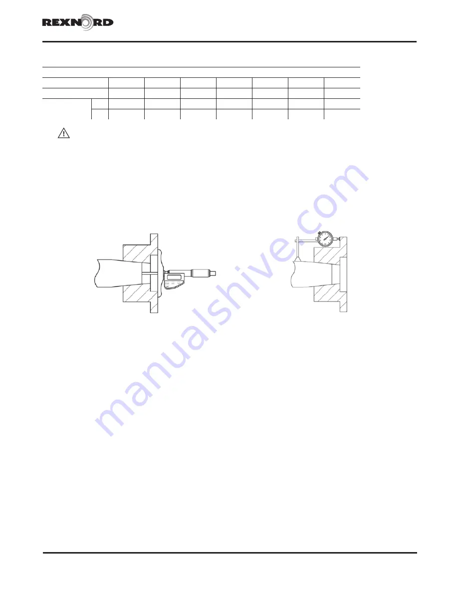
Figure 3 -
Shaft end to hub face measurement example.
Figure 4
- Dial indicator placement for axial draw
measurement example.
7. Taper Bore
7.1. Check for acceptable contact pattern between the hub and the shaft.
7.2. Put the hub on the shaft, keeping the keyways (if existing) aligned.
7.3. Lightly tap the face of the hub with a soft mallet. The resultant position will provide a starting point for the hub axial draw up.
7.4. Use a depth micrometer to measure the distance from the shaft end to the hub face, as shown in Figure 3. Record the dimension.
7.5. Mount a dial indicator to read axial hub advancement, as shown in Figure 4. Alternatively, the indicator can be positioned to contact the
end of the hub. Set the indicator to “zero”.
7.6. Remove the hub and install the key(s) in the shaft.
7.7. Heat the hub in an oven until the bore is sufficiently larger than the shaft.
7.8. 350°F (177°C) is usually sufficient for carbon steel hubs. Do not exceed 500°F (260°C).
7.9. Higher temperatures may be required for higher interference fit levels where alloy steel hubs may be encountered. A general rule to
consider is that for every 160°F increase in temperature, steel will expand 0.001 inch for every inch of shaft diameter (or 0.029 mm/100°C).
When calculating temperatures, also consider additional expansion to provide clearance and allow for a loss of heat and subsequent
shrinkage during the handling process.
7.10. With the hub expanded, install it quickly on the shaft to the “zero” set point. Continue to advance the hub up the taper to the desired
axial position, as defined by Rexnord’s customer. Use the indicator as a guide only. A pre-set axial stop device can be helpful.
7.11. Inspect the assembly to verify that the hub is properly positioned. Consult Rexnord if necessary.
7.12. Install any hub axial retention device (if any) in accordance with the equipment manufacturer’s specifications.
Table 2 - Set Screw Tightening Torque
Screw Size
M6
M8
M10
M12
M16
1/4"
3/8"
Hex Head Key Size
M3
M4
M5
M6
M8
1/8"
3/16"
Tightening torque
Nm
6
12
25
50
100
8
25
lb-in
55
110
220
440
880
70
220


