General Instructions
BACKSTOP-SHAFT FITS —
The shaft must have a 125 micro
inch (3,2 micro meters) or finer finish and clearance fits
specified in Table 3 above.
KEYS & KEYWAYS —
Keys to be used with 1055, 1065, &
1085 NRTH backstops are furnished by Rexnord. They are
mild steel. The keys are side-fitted, full length, and must not be
excessively tight in order to avoid distortion of the inner race.
BACKSTOP MOUNTING POSITIONS —
The backstop
rotational axis must be horizontal within 5° for all applications.
The
NRTH backstop
torque arm is capable of being mounted
at any desired angle, however a horizontal mounting at 0° or
180° is preferred.
TORQUE ARM STOPS (OR STIRRUP) —
The torque arm
stops must be designed to resist the force developed by the
actual torque applied to the backstop.
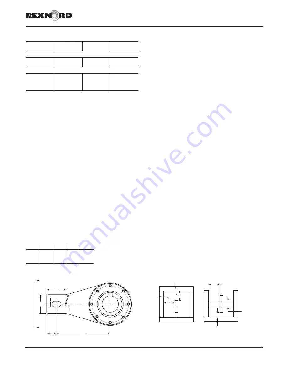
The minimum recommended distance to the torque arm stop
is as illustrated in Figure 2 below. Use torque arm stops
capable of withstanding the torque arm reaction force. (See
Table 2)
The torque arm must be free to move within the stirrup or on
pin. Provide clearance on three sides per Figure 2 below.
DO NOT restrict torque arm movement by welding or securing
the torque arm to any supporting structure.
Locate the torque arm support surface parallel (±1/2°) to the
torque arm surface.
Prevent accumulation of any foreign material or ice around
torque arm and torque arm stirrup which could restrict free
movement of the torque arm.
Long Term Storage
Backstop should be completely filled with Dexron III automatic
transmission fluid. Backstops should be stored inside, if
possible, in a clean and dry area. Once every two months the
inner race should be rotated by hand to lubricate the rotating
elements.
Exposed, unpainted surfaces should be “brush painted” with a
rust preventative.
Before placing the backstop in operation, completely drain
and properly refill per lubrication section on Page 4.
Installation
A. Check for proper free shaft rotation - The backstop is
symmetrical, which allows it to be mounted for the desired
direction of free shaft rotation by rotating it end for end.
The arrow inscribed on the face of the inner race (Part #1)
indicates the direction of free shaft rotation. Before
mounting the backstop on the shaft, be sure to check
direction of free rotation.
B. Axial Retention - Since backstops are not a tight fit on
shafts, it is important to utilize the inner race setscrews (Part
#12) to prevent the backstop from “walking” on the shaft,
as this may cause end of the torque arm to contact the
stirrup and cause premature bearing failure.
After the backstop is mounted on the shaft, tighten all (4)
setscrews in the inner race. In the event that the backstop is
to overhang the shaft, it is permissible to only tighten the
two inboard setscrews. Setscrews should be tightened to
5-7 Lb-Ft.
C. Mount Backstop on Shaft - Backstop bores are finished to
size for an
easy push fit
on a shaft that is straight and not
tapered.
Coat the shaft with an anti-seizing agent or light oil for
easy mounting and future removal of the backstop.
Check again to
make certain
that the arrow on the
backstop inner race face is in the same direction as the
desired free shaft rotation.
If the torque arm (Part #15) is to be mounted on the
inboard
face of the backstop, then slip torque arm onto the
shaft
prior
to mounting the backstop.
Push the backstop onto the shaft, taking care to push only
on the face of the inner race, thus eliminating undue abuse
on the bearings within the backstop.
Rexnord Industries, LLC, Geared Products, P.O. Box 492, Zip 53201-0492
568-102
3001 W. Canal St., Zip 53208-4200, Milwaukee, WI USA Telephone: 414-342-3131
July 2006
Fax: 414-937-4359 e-mail: [email protected] web: www.rexnord.com
Supersedes 2-05
Falk™ Horizontal Shaft Backstops
•
Installation & Maintenance
Type NRTH Style B
•
Sizes 1055, 1065, & 1085
(Page 3 of 4)
K
J
F
1.25
0.5" TO 1.0”
CLEARANCE
BOTH SIDES
.50” CLEARANCE
0.75” CLEARANCE
1.125
PIN DIA.
0.5" TO 1.0”
CLEARANCE
BOTH SIDES
ARM RETENTION
PIN RETENTION
+.000
– .010
A
A
E
REQUIRED FOR SIZE 1085
TABLE 3 — Backstop Shaft Fits
Nominal
Diameter
Nominal Shaft
Tolerance
Nominal Bore
Dia Tolerance
Bore - Shaft Min-
Max Clearances
Inch
1.7500-2.9375
+.0000, –.0010
+.0005, +.0015
.0005 – .0025
3.0000-5.4375
+.0000, –.0010
+.0010, +.0025
.0010 – .0035
Metric
45 to 50 k6
.002/.018 k6
.025/.050 F7
.007/.048
50 to 80 m6
.011/.030 m6
.060/.090 E7
.030/.079
80 to 120 m6
.013/.035 m6
.072/.107 E7
.037/.094
120 to 140 m6
.015/.040 m6
.085/.125 E7
.045/.110
Figure 2
View A - A
SIZE
E
F
J
K
1055
2
36
4
4
1065
2
36
4
4
1085
5
51
6
10


