background image

30


Wireless NVR Kit Manual


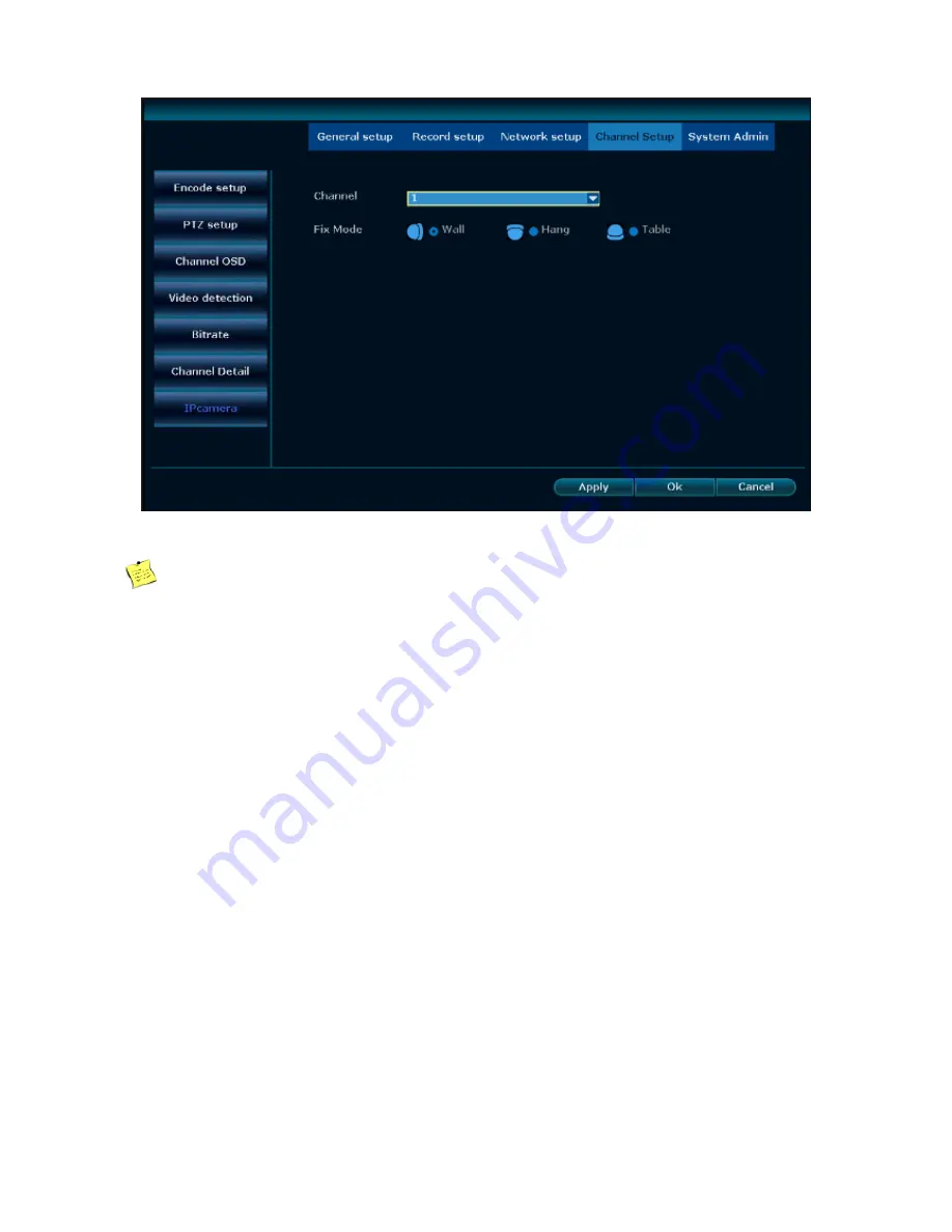
 2, Select the corresponding channel, the installation mode can choose wall, hanging, desktop 

       Explanation 


The installation mode can be selected only when the panorama camera is connected 


Currently can support the Panoramic cameras which support the N1 protocol 

4.4 Network setup 

4.4.1. Network setup 

Explanation

If  the  device  is  used  for  network  monitoring,  the  network  must  be  set  up  for  normal  use.  Factory 

default IP address: 192.168.1.114.


Steps


1, Right click the main interface, in the shortcut menu, select the system setup, and then select the network setup. The 

basic setup for the network setup is shown below: 

Summary of Contents for RW4NVR1

Page 1: ...1 Wireless NVR Kit Manual REVO Wireless Network Video Recorder Model RW4NVR1 Product Manual...

Page 2: ...uctions 5 2 5The remote control operating instructions 6 2 6Interface specification 7 2 6 1Interface elements specification 7 2 6 2Commonly used buttons instructions 8 2 7Menu description 8 3 Installa...

Page 3: ...it channel 4 3 7Encoding setup 20 4 3 8Code stream value 21 4 3 9 Channels in detail 21 4 3 10 Channel OSD 22 4 3 11 Camera 23 4 4 Network Setup 23 4 4 1 Network Setup 23 4 4 2 Dynamic DNS 25 4 4 3 FT...

Page 4: ...ral setup 37 4 10 2Timeset 38 4 10 3Screen setup 39 4 10 4Hard disk setup 39 4 10 5Exception settings 41 4 11Device maintenance and management 41 4 11 1 System information 41 4 11 2 User management 43...

Page 5: ...Wireless NVR Kit Manual 5 3 1 Cloud ID login 52 5 3 2 The user name login 53 6 Mobile terminal access 53 7 Appendix 58 7 1Hard disk capacity unit conversion 58 7 2Video required capacity calculation 5...

Page 6: ...ponents and accessories mentioned in this manual are for illustrative purposes only and do not represent the configuration of the purchase model Please refer to the packing list for details Special st...

Page 7: ...RW4NVR1 Video input 4ch D1 960H720P 960P 1080P HDMI Output 1ch Resolution 1024x768 1280x1024 1366x768 1440x900 1920x1080 VGA Output 1ch Resolution 1024x768 1280x1024 1366x768 1440x900 1920x1080p Reso...

Page 8: ...ireless NVR Built in high performance and high stability wireless Wi Fi routing module supports 802 11b g n protocol 150Mbps Can automatically access the Wi Fi network camera through the network cable...

Page 9: ...IPC to support video motion detection Collaborate with IPC to support video masking Support user rights management 2 Operation explanation 2 1 The front panel explanation Figure 1 1 POW Power indicat...

Page 10: ...Click twice Window zoom 1 switch between a single interface and the multi interface in previewing 2 add device Drag Set the area 1 set the motion detection area 2 select the electronic amplification a...

Page 11: ...Input method instructions Figure 3 Name Key instructions Function instructions Number 0 9 Input number 0 9 Character _ Enter the punctuation Capital lower case caps Letter case switch Backspace Remov...

Page 12: ...ontrol of the device will take effect 0 9 number keys MENU Menu key Clears all areas when setting the motion detection area ESC Exit key In the menu mode select up in PTZ mode control the dome camera...

Page 13: ...6 1Interface elements specification Name Operation Operation function Example Button click on the left mouse Save or cancel Application confirmation cancellation Open the sub interface Edit set Edit b...

Page 14: ...ower supply voltage cannot exceed the power supply of the normal operating voltage range 3 2 Preparation before installation 1 Determine the installation location of the NVR It is recommended that the...

Page 15: ...o indication that any network cable is bad please re connect to the code matching operation disconnect the network cable to see if the screen is normal the screen normal means that the wireless camera...

Page 16: ...of the wireless signal install wireless camera 2 Power the wireless camera for 1 minute or so you can see the video in the NVR monitor 3 If it does not show the image this may be indicating that the...

Page 17: ...the access voltage matches the requirements of the NVR and that the NVR is well grounded When power supply is abnormal it will cause the hard disk video recorder to not work or even damage the NVR it...

Page 18: ...1 2 Login When the system is powered on and started after waiting for the system to initialize the system will automatically pop up the login interface As shown below The user needs to complete the l...

Page 19: ...If a user needs to log out you can right click shortcut menu select exit system Click the user to log off then you can complete As shown below If the user needs to log off automatically in the system...

Page 20: ...etup Wizard interface guide the user to set the basic settings so that the device can work properly Steps 1 Set the wizard You can set whether to turn on the boot wizard Set the interface as shown bel...

Page 21: ...tically obtain IP address manually set the IP address gateway mask PPPoE and other operations Operation interface as shown below after the operation is complete click the next step to continue the wiz...

Page 22: ...esponding hard disk then click the format button Wait a moment then you can format the selected hard disk the hard disk format status will also be displayed as formatted Operation interface as shown b...

Page 23: ...t interface and click the refresh button to complete the search IPC device operation The figure looks like this 4 3 2 Add device Function instructions Used to add the searched IPC device Operation ste...

Page 24: ...If the code matching fails please click Refresh If no device is indicated then it means the network cable is poorly connected Please re connect to do the code matching operation 3 Fast adding After th...

Page 25: ...p Support multi network segment search allowing repeated adding smart adding Steps Right click the system main interface in the pop up right click menu select Video Management In the open video manage...

Page 26: ...Used to delete an added device Steps 1 Right click on the main interface of the system in the pop up right click menu selecting Video Management After entering the video management interface click to...

Page 27: ...another IPC to send the video to the NVR thereby increasing the wireless transmission distance and extending the covering range of the wireless kit Steps 1 Right click on NVR S GUI left click video ma...

Page 28: ...As the picture shows below it means IPC1 is connected to NVR through IPC2 and IPC3 IPC2 is connected to NVR through IPC3 IPC3 is connected to NVR directly 4 Click Apply and then click refresh to chec...

Page 29: ...e Operational steps 1 Right click on the main interface of the system in the pop up menu right click Video Management in the open video management interface click to select any of the IPC device which...

Page 30: ...coding level and so on Operational steps 1 Right click on the main interface of the system in the pop up menu right click Video Management Enter the video management interface click to select any of t...

Page 31: ...s the device self adaptation will select the secondary stream to ensure the fluency of the monitor Resolution has 720 576 960 576 1280 720 and other grades can choose the higher the resolution the bet...

Page 32: ...on Check the device name resolution stream value video frame rate and software version of the IPC device in each channel Steps 1 Right click the main interface in the shortcut menu select the system s...

Page 33: ...and change the currently displayed channel name Enable the status display and the communication quality the icon of the communication situation is displayed in the multi screen of the main interface...

Page 34: ...ht and soft 3 Select the display setup enter the location of communication icon adjustment Can select position and magnification 4 3 11 Camera Functional explanation You can set the panorama camera in...

Page 35: ...ly can support the Panoramic cameras which support the N1 protocol 4 4 Network setup 4 4 1 Network setup Explanation If the device is used for network monitoring the network must be set up for normal...

Page 36: ...the IP address of the device if you set the IP address manually you can manually enter the IP address When you cancel the Automatically getting IP checking box button you can manually set the IP E see...

Page 37: ...Network status Notify the current network status If the ID number is not online it can be operated according to the notifying information 4 4 2 Dynamic domain name Function explanation If the device d...

Page 38: ...settings and then select the network setup FTP As shown below 2 Check the FTP function to open the check box 3 Fill in the FTP host port user name and password and other information 4 Set the time per...

Page 39: ...d Email Password Encryption type The default can choose to not select if the test fails then modify to SSL Sender The sender s full email address need to be consistent with the user name for example12...

Page 40: ...t dial up Internet access Steps 1 Right click the main interface in the shortcut menu select the network setup PPPoE As shown below 2 Check the Enable box in the edit box enter the user name and passw...

Page 41: ...box 3 Fill in the dialing number APN PIN user name and password and other information 4 Click the Apply button to save the setup 4 4 7 Wireless setup Steps 1 Right click the main interface in the sho...

Page 42: ...erequisites Before the user controls the IP channel or the PTZ please make sure that the network between the PTZ decoder and the NVR is connected normally in advance and that the device PTZ decoder pa...

Page 43: ...Select the baud rate which matching the connected PTZ Copy to In the right selecting box of the copy to button select the target channel click the copy set to button the system will apply the current...

Page 44: ...t the system setup and then select the PTZ setup in the channel setup 2 Click on the right side of the preset button to enter the control interface set the preset point 3 Select the preset position an...

Page 45: ...shown below 2 Check the channel you want to record 3 To enable manual recording for all channels click the Open All button 4 To turn off manual recording for all channels click the Close all button 5...

Page 46: ...hours recording you only need to set the time period 1 from zero to 24 o clock other time periods do not need to be set The time period set by the user will be displayed in color bar User can visuall...

Page 47: ...ault sensitivity for video detection is higher 4 6 4 Alarm recording Function explanation Turn on the alarm recording function the system will record when detecting the alarm input Steps 1 Right click...

Page 48: ...eat the above steps If the other alarm inputs are consistent with this alarm input setup select the channel and click the Copy to button 4 7 Video playback 4 7 1 Fast playback Function explanation Ope...

Page 49: ...3 Check the channel which needs to be retrieved and the recording mode 4 Set the search period and click the Search button 5 Waiting about 30 seconds in the retrieved video drag the play bar to the p...

Page 50: ...ht click the main interface select video backup in the shortcut menu and enter the video backup interface As shown below 3 Check the channel you want to retrieve and select the recording mode 4 Set th...

Page 51: ...deo backup make sure the USB flash disk has enough storage space 4 9 Alarm 4 9 1Motion detection alarm Function description When an object is detected in the selected screen the device will trigger an...

Page 52: ...le detection processing methods are alarm buzzer E Mail notification and mobile phone APP alarm If you choose the alarm for the motion detection processing mode you need to select the work mode as nor...

Page 53: ...ation If the other channel setup are the same as the channel select the channel and click Copy to 4 10 General Setups 4 10 1General Setups Function explanation Make setups for frequently used function...

Page 54: ...language of the different countries as needed Remote control switch Select whether to allow remote control using Boot wizard Select whether to enable the wizard when starting up Show the e see net ID...

Page 55: ...50 Wireless NVR Kit Manual 4 10 3 Screen setup Function explanation Set the screen parameters Steps Right click the main interface select the system setup General Setup screen setup...

Page 56: ...ency of the interface VGA Resolution Select the resolution that will adapt to the screen Automatic cruise Whether to open the cruise and set the time Explanation Skip Video Loss means that no image wi...

Page 57: ...cally select User defined in the drop down box and fill in the number of days 7 Click the Apply button to save the setups Explanation Check the automatic coverage means that the hard disk will automat...

Page 58: ...m setup interface 2 Select the General Setup hard disk setup As shown below 3 Select the exception type click Open and select the alarm mode 4 Click Apply to save the setup 4 11 Equipment maintenance...

Page 59: ...gnificance the user needs to provide the appropriate version information when in need of maintenance Hard disk information Function explanation The user can check all the hard disk models the device h...

Page 60: ...55 Wireless NVR Kit Manual Log information Function explanation The user can check the corresponding log information according to the time type start time and end time As shown below...

Page 61: ...you can view the corresponding log information Explanation Click on the next page to read the log Log stored in the hard disk the log information will be lost after the hard disk formatted The time t...

Page 62: ...Add the user Steps 1 Right click the main interface in the shortcut menu select the system setup and then select the system management user management 2 Click the New User button to enter the New Use...

Page 63: ...pen the video at any time System setup Contains general setup video setup network setup channel setup and system management Split screen selection Single screen and multi screen switch Channel adjustm...

Page 64: ...list Explanation Super users cannot be deleted Edit user Steps 1 Right click the main interface in the shortcut menu select the system setup and then select the system management user management 2 Le...

Page 65: ...1 Right click the main interface in the shortcut menu select the system setup and then select the system management user management 2 Left click and select the user name and click the Change Password...

Page 66: ...the system setup and then select the system management factory setup As shown below 2 Check the option that needs to restore factory setups and click the Apply button 3 Select the OK button in the pro...

Page 67: ...Start 4 In the progress bar you can see the progress of the system upgrade wait for the system upgrade to complete the device will then restart Method 2 1 Right click the main interface using fast ne...

Page 68: ...de please ensure that the device has been successfully connected Online upgrade can be customized server address port and network path 4 11 6 IPC Maintenance Function explanation IPC maintenance using...

Page 69: ...ure 5WEB Access 5 1 Introduction Product embedded WEB server support remote WEB access After the device is connected to the network the user enters the IP address of the device in the browser address...

Page 70: ...and password correctly 4 Click Login to enter the preview interface As shown below 5 The first time you follow the prompts to download and run the WebClient exe control As shown below 6 Log in again...

Page 71: ...dress in the browser you need to enter the port number after the address such as 192 168 1 28 102 If you cannot load the software for the first time you need to see the following setups for the browse...

Page 72: ...ort 1 4 9 16 25 36 screen segmentation Support the main stream sub stream selection 5 2 3 Playback Specific steps 1 Click the playback icon in the preview interface 2 Enter the playback interface as s...

Page 73: ...en a non super user logs in please make sure that the user has remote playback permission You can check and give users a remote video playback permission in the System Setup System Administration User...

Page 74: ...configuration rights in System Management User Management Edit User 5 3 Revowireless net access 5 3 1 Revowireless Cloud ID login Steps 1 Open the browser 2 Input http www revowireless com As shown b...

Page 75: ...2 Enter http www revowireless com Select User name login as shown below 3 The first time you can register according to the prompt information after registration and then log in Explanation Support Ch...

Page 76: ...the user name and password information enter the mailbox mailbox for forgetting the password to retrieve the password you can skip you can also click local to enter the mobile client to add equipment...

Page 77: ...tion As shown below Explanation Click Add device can choose cloud ID IP DDNS LAN scan After the account login system automatically identify the number of ID click submission after adding then complete...

Page 78: ...d at the same time support 4 6 8 9 13 16 screen split to preview at the same time If the PTZ control is supported can use the PTZ control button to operate 5 Remote playback In the preview interface c...

Page 79: ...riod of time click the channel to select a specific channel Support 1 channel playback If the video has sound the playback will also have sound Click on the video can be recorded when playback video s...

Page 80: ...he video in your phone Click on the picture quality can choose HD or SD HD is the main stream SD is sub stream 7 Mobile phone APP alarm Click me enter the operation interface select alarm setup and op...

Page 81: ...76 Wireless NVR Kit Manual...

Page 82: ...capacity conversion B 1 B 8 b B 1 B 8 b MB 1 MB 1000 KB MB 1 MB 1024 KB GB 1 GB 1000 MB GB 1 GB 1024 MB TB 1 TB 1000 GB TB 1 TB 1024 GB Explanation The capacity conversion of this device is the same w...

Reviews: