REV-11-1200-UM-02
Copyright © 2016 REV Robotics, LLC
6
2.2
HEADERS
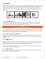
Each MXP signal pin is broken out to sets of 0.1" pin-headers. Every Digital IO (DIO), Analog Input, and Analog Output is
brought out to 3-pin headers with the standard servo-style pinout: [GROUND][POWER][SIGNAL]. Serial interfaces shared
with DIO, I
2
C and SPI, are also brought out to single line headers. UART is only brought out in a single line header
because it is not shared with any DIO. Each signal is labeled next to its corresponding header group. Figure 2-1 shows
these pinouts.
Figure 2-1 Header Pinouts
2.2.1
PWM CONNECTIONS
PWM signals are shared with several DIO on the MXP. These signals, like all MXP signals, are passed through and
broken out without any intermediate active circuitry. For example, these PWM connections can be used to safely
connect motor controllers, keeping their PWM signals under control of the roboRIO.
CAUTION
Do not connect Servo Motors to the More Board.
The MXP and the More Board are not designed to provide power to Servo Motors. Even though 5.0V or 3.3V is provided
on the middle pin of the 3-pin headers, the required 6.0V is not brought out through the MXP and therefore not available
on the More Board. Servos must be connected to the roboRIO PWM ports.
2.2.2
MXP PASS-THROUGH CONNECTOR
All MXP signals are routed to a female MXP header (J4) at the bottom edge of the More Board. Every signal is passed
through this connector so that additional MXP accessories can be connected with the REV Robotics MXP Extension
Cable (REV-11-1118).
2.3
POWER RAILS
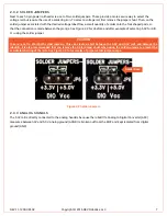
The MXP can provide both 5.0V and 3.3V to connected expansion boards. Four separate rails exist on the More Board,
each with the ability to use the MXP 5.0V or 3.3V. These four rails are DIO VCC, I
2
C V
CC
, SPI V
CC
, and UART V
CC
. Each rail
has two methods of selecting the supplied voltage: a jumper shunt and a solder jumper.
Both the 5.0V and 3.3V rails can be disconnected with jumpers JP16 and JP14, respectively. This makes it possible to
connect an external power source to these rails.
2.3.1
JUMPER SHUNTS
The 2-pin jumper shunts are installed on 3-pin headers and connect the middle pin to one of the outer pins. Move the
jumper to the side labeled with the desired voltage.


