background image


Revision 2.1D 


Page 7 of 14 


www.resourcedm.com 

Mercury Switch User Guide


Warning 


Please Note 

The specifications of the product detailed on this 
Set-Up  Guide  may change without notice. RDM 
Ltd. shall not be liable for errors or for incidental 
or consequential damages, directly and indirectly, 
in connection with the furnishing, performance or 
misuse of this product or document.


Ensure that all power is 
switched off before   
installing or maintaining 
this product 

IP-L (Local IP Address) 

 
To configure the Mercury Switch for IP-L, set both rotary switches to zero.  
 

1. 

nEt. From the function menu you can now select nEt 


Press enter and the display will show  “IP-L”, press enter 


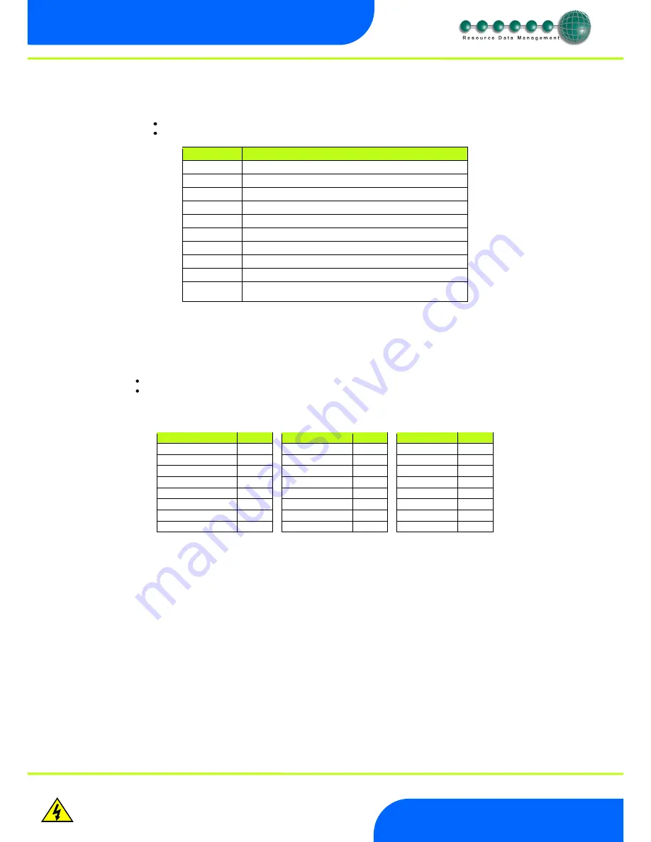
You can now set the address using the table below 


Display


Option


IP-1 

IP Address byte 1 

IP-2 

IP Address byte 2 

IP-3 

IP Address byte 3 

IP-4 

IP Address byte 4 

nL 

Network Mask Length 

gt-1 

Gateway Address byte 1 

gt-2 

Gateway Address byte 2 

gt-3 

Gateway Address byte 3 

gt-4 

Gateway Address byte 4 

ESC 

Exit network menu. 

N.B.

 this option 

must

 be selected to save 

any changes made in this menu 


IP-r (IP Address issued by the DHCP server) 

 
To configure the Mercury Switch for IP-r, set the two rotary switches to give each controller a unique identifier. The controller should then 
be connected to the network. 
 

2. 

nEt. From the function menu you can now select nEt 


Press enter and the display will show  “IP-r”, press enter 


You can now view only the address given by the DHCP server 

 
To ease setup, a single network mask length value is used. If the address has been specified with a network mask value in dotted IP 
format e.g. 255.255.255.0 then the table below gives the conversion: 
 

Mask


Length


Mask


Length


Mask


Length


255.255.254.0 

23 


255.254.0.0 

15 

255.255.255.252 

30 


255.255.252.0 

22 


255.252.0.0 

14 

255.255.255.248 

29 


255.255.248.0 

21 


255.248.0.0 

13 

255.255.255.240 

28 


255.255.240.0 

20 


255.240.0.0 

12 

255.255.255.224 

27 


255.255.224.0 

19 


255.224.0.0 

11 

255.255.255.192 

26 


255.255.192.0 

18 


255.192.0.0 

10 

255.255.255.128 

25 


255.255.128.0 

17 


255.128.0.0 

09 

255.255.255.0 

24 


255.255.0.0 

16 


255.0.0.0 

08 


Summary of Contents for Mercury PR0018

Page 1: ...ercury Switch User Guide Resource Data Management Ltd 80 Johnstone Avenue Hillington Industrial Estate Glasgow Scotland G52 4NZ UK 44 0 141 810 2828 Switchboard support resourcedm com Technical Suppor...

Page 2: ...Setup via Display 5 Recommended set up method 6 Set View Type 6 Set View Parameters This can also be achieved at the network front end 6 ID 6 Network Configuration 6 IP L Local IP Address 7 IP r IP Ad...

Page 3: ...s As well as the Switch function there is the option for Island EEV control This control can be achieved by using a transducer connected to the Mercury Switch 4 20mA input or from a remote Suction pre...

Page 4: ...elf configuring Connection to a Data Manager Director Use a standard CAT5 patch lead and connect the Data Manager or Data Director to one of the 3 10 Base T ports 10 100 Base T connectors The three 10...

Page 5: ...splay The display fits a standard UK single socket pattress Enter Button Button used to enter confirm values after a change Up Button When in the software menu the up button is used to scroll up throu...

Page 6: ...press Enter again to save the value The parameter list number will be displayed again Two other options are present in the parameter menu dFLt and ESC Selecting ESC will exit setup mode Selecting dFLt...

Page 7: ...ed by the DHCP server To configure the Mercury Switch for IP r set the two rotary switches to give each controller a unique identifier The controller should then be connected to the network 2 nEt From...

Page 8: ...5 0 to 7 2 0 1 Bar Psi 0 1 P 17 Evap 7 offset 0 0 to 0 5 0 to 7 2 0 1 Bar Psi 0 1 P 18 Evap 8 offset 0 0 to 0 5 0 to 7 2 0 1 Bar Psi 0 1 P 19 Evap 9 offset 0 0 to 0 5 0 to 7 2 0 1 Bar Psi 0 1 P 20 Ev...

Page 9: ...educed to a predetermined percentage A MOP alarm is also created See MOP P 41 MOP Diff When the pressure reduces below this value valves on controllers connected to the Switch will recover to their no...

Page 10: ...te 1 Temperature 49 0 to 60 56 2 to 140 0 o C o F O 34 Remote 2 Temperature 49 0 to 60 56 2 to 140 0 o C o F O 35 Remote 3 Temperature 49 0 to 60 56 2 to 140 0 o C o F EEV Control Operation Product PR...

Page 11: ...ury Switch Or the remote Mercury Plant Controller The Mercury Case controllers require to have P17 Evaporator control set to 1 Remote for this feature to function Mercury Switch Type There are 4 types...

Page 12: ...et to Remote and the Data Manager GP timer channel directed to the Mercury Switch is in the on period the humidity control will operate as described above During the Data Manager GP timer channel off...

Page 13: ...to the Mercury Switch WebPages This can be achieved by using the Controller Info page in the Data Manager Data Director Find the IP address assigned to the Mercury Switch in question from the list No...

Page 14: ...in the UK manufactured in Taiwan Ventilation There is no requirement for forced cooling ventilation Class 2 Insulation No protective Earth is required and none should be fitted The host equipment must...

Reviews: