RENOLD jPM 17 A 71 2.0 R 30 Installation & Maintenance Manual Download Page 16

def


jPM Series 


Gears 


INSTALLATION & MAINTENANCE GUIDE 


16

Appendix C 


MOTOR CIRCUIT DIAGRAMS 

 
The following motor circuit diagrams are relevant for jPM Series gear units supplied with our standard 
motors already fitted. For motor ready gear units, please refer to the motor supplier’s installation and 
maintenance instructions for that particular motor. 
 
Standard motors are provided with a terminal box, which contains six connections, to which six leads 
from the winding are connected either in a delta connection, or in a star connection by means of metallic 
connection links. 
 
Usually, two voltages will be displayed on the rating plate of the motor. This means that the motor can be 
connected to a circuit which has one of these voltages. If the mains voltage corresponds to the lowest 
indicated voltage shown on the rating plate, then the motor winding has to be connected as a Delta 
connection (refer to C.1). However, if the mains supply has a voltage equalling the highest indicated 
voltage as shown on the rating plate, then the motor must be connected as a Star connection (refer to C.2). 
For example, a motor with 230/400V indicated on its rating plate, is suited either to a circuit with a 
voltage of 230V with the winding connected in a Delta connection; or on a circuit with a voltage of 400V 
with the winding connected in a Star connection. 
 
For pole change motors (for two or more speeds) and brake motors, please refer to the wiring connection 
diagram which will be sent with the motorised gear unit. 
 

WARNING: 

Electrical connections should only be carried out by a fully qualified electrician.
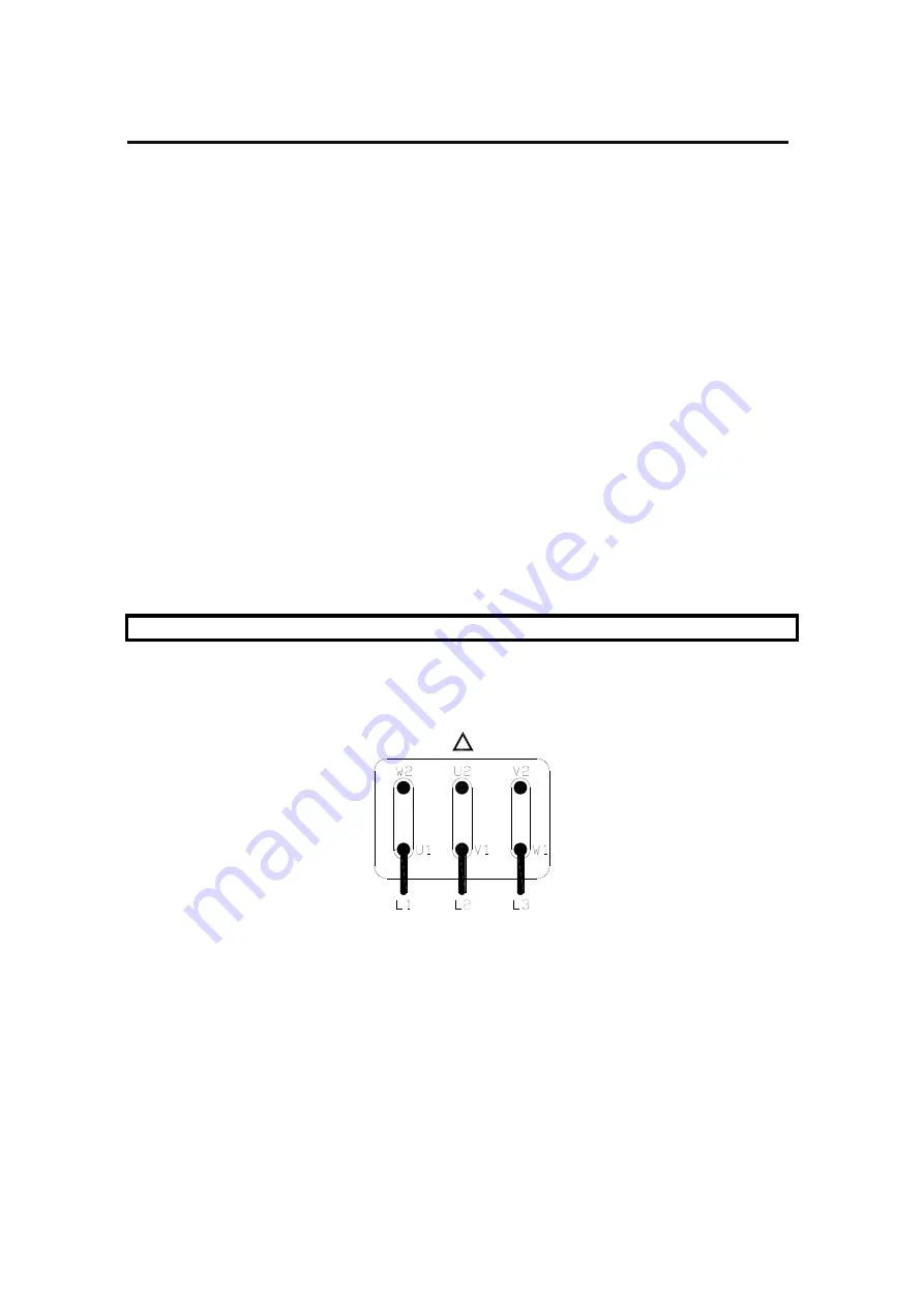


C.1 

Delta Connection Procedure 

 
To complete a Delta connection: 


I.


Link W2-U1, U2-V1 and V2-W1 using the metallic strips provided. 

 
II.


Connect Line 1 (L1) to U1, Line 2 (L2) to V1 and Line 3 (L3) to W1. 

 
III.


Connect the Earth wire to the separate terminal supplied. 

 
IV.


Turn on the power supply and check the direction of rotation. 

 
V.


If the direction of rotation is incorrect, swap over any two of the “line - in” wires. For example, Line 1 
(L1) to V1 and Line 2 (L2) to U1, etc. 

Summary of Contents for jPM 17 A 71 2.0 R 30

Page 1: ...def jPM SERIES GEAR UNITS SINGLE REDUCTION WORMGEAR UNITS INSTALLATION MAINTENANCE GUIDE March 2010...

Page 2: ...nning temperatures can burn or melt rubber compounds and melt plastic compounds and produce dangerous fumes These compounds should be avoided until cool and then handled with protective gloves Guards...

Page 3: ...ts 5 7 Installing Shaft Mounted Gear Units Turnbuckle Restraint 5 8 Installing Shaft Mounted Gear Units Torque Restraint Bracket 6 Lubrication 9 6 1 Gear Unit Lubrication Requirements 6 2 Lubrication...

Page 4: ...ers to fit their own motors Rated up to 397 Nm in a ratio range from 5 1 up to 70 1 jPM Series as a single reduction gear unit and offers a wide selection of mounting options and accessories to suit a...

Page 5: ...order 5 1 FITTING OF COMPONENTS ONTO INPUT OUTPUT SHAFTS Components which are to be fitted to either the input or output shaft of the gear unit e g couplings pulleys sprockets etc may be fitted using...

Page 6: ...tor identification plate NOTE The correct sizing of cables to electrical regulations is essential Motor Where units are supplied with motors connection to the motor terminal box should be carried out...

Page 7: ...its I Firstly ensure that the foundation where the unit is to be positioned is suitable as stated in Section 4 3 and is not distorted II Locate the unit in the appropriate mounting position III Secure...

Page 8: ...the torque arm pivot pin as shown on the next page This angle may vary up to a maximum of 30o in either direction where necessary NOTE The torque arm should be in tension rather than in compression wh...

Page 9: ...this has an operational life equivalent to that of the gears Oil changes are therefore unnecessary NOTE Units are supplied with oil for the mounting position specified on the order 6 1 GEAR UNIT LUBR...

Page 10: ...e is free from dirt or grease Clean if required II Check for any lubricant leaking from the unit Leakage from any of the plugs in the unit can be solved by removing the plug drain the unit if necessar...

Page 11: ...d with a anti corrosion rust inhibitor III After spraying all shafts should be wrapped in anti corrosion rust inhibitor paper IV Where the unit is empty of oil spray the gearcase interior with rust pr...

Page 12: ...never exceed 5mm Plastic parts should be wiped clean with a damp cloth Oil leaks should be dealt with as quickly as practical Compound joint faces and shims should be cleaned and thread locking sealan...

Page 13: ...def jPM Series Gears INSTALLATION MAINTENANCE GUIDE 13 Appendix A JPM SERIES TYPE SINGLE REDUCTION WORM GEAR UNIT MOUNTING CODES...

Page 14: ...il level plugs and drain plugs The customer should familiarise themselves with the positions of the plugs for the applicable mounting position of the gear unit This information will be required prior...

Page 15: ...def jPM Series Gears INSTALLATION MAINTENANCE GUIDE 15 Appendix B SHAFT END TAPPED HOLE DETAIL...

Page 16: ...ains supply has a voltage equalling the highest indicated voltage as shown on the rating plate then the motor must be connected as a Star connection refer to C 2 For example a motor with 230 400V indi...

Page 17: ...r any two of the line in wires For example Line 1 L1 to V1 and Line 2 L2 to U1 etc C 3 Star Delta Connection Procedure If the motor is to be used with a Star Delta starter then the motor is only to be...

Page 18: ...ner I Obtain a slip block which is marginally smaller than the gap between the two coupling halves Mark a datum point on both coupling halves II Position the datum mark in Position A as shown on the d...

Page 19: ...and adjust the indicator to read zero IV Rotate the coupling half which is carrying the D T I until Position B is reached Observe and record the fluctuation in dial reading The amount of vertical corr...

Page 20: ...catalogue rating with temperatures up to 100o C Heavy grade oils should be used at temperatures in excess of 100o C under heavy loading However if the unit is operating at gear rubbing speeds below 2...

Page 21: ...def jPM Series Gears INSTALLATION MAINTENANCE GUIDE 21...

Page 22: ...def jPM Series Gears INSTALLATION MAINTENANCE GUIDE 22...

Page 23: ...unning temperatures can burn or melt rubber compounds and melt plastic compounds and produce dangerous fumes These compounds should be avoided until cool and then handled with protective gloves Guards...

Page 24: ...com FRANCE Brampton Renold TEL 33 0 320 16 29 29 FAX 33 0 320 16 29 00 GERMANY Renold Getriebe Kupplungen TEL 49 0 2256 959074 FAX 49 0 2256 959169 EMAIL renold deutschland renold com HOLLAND Renold...

Reviews: