


VIONiC RTLC20-S installation guide
11
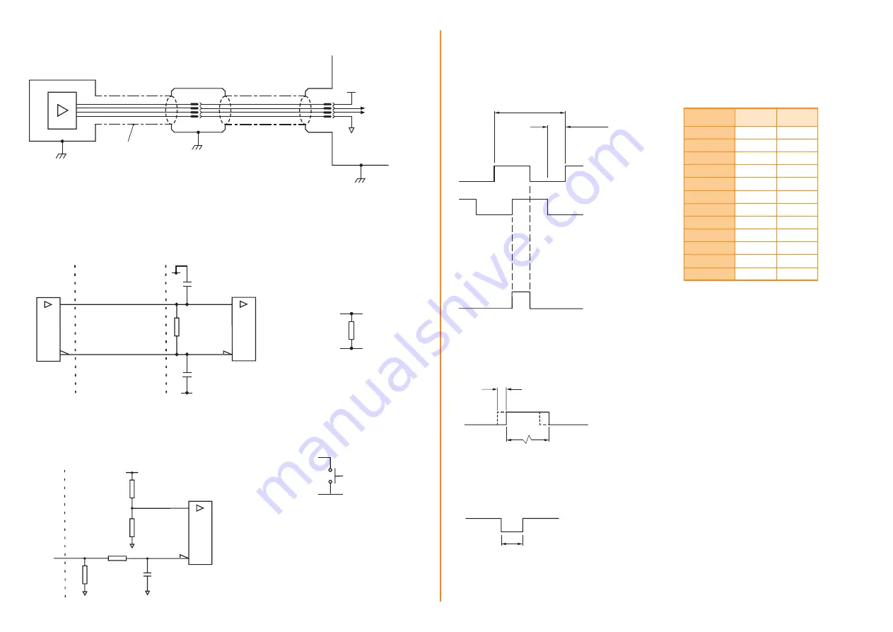
Electrical connections
Grounding and shielding
Shield
Output
signals
5 V
Readhead
termination/connector
0 V
Customer
electronics
VIONiC readhead
IMPORTANT:
The shield should be connected to the machine earth (Field Ground).
For JST variants the ferrule should be connected to machine earth.
Maximum readhead cable length:
3 m
Maximum extension cable length:
Dependent on cable type, readhead cable length and clock speed.
Contact your local Renishaw representative for more information.
Recommended signal termination
Standard RS422A line receiver circuitry.
Capacitors recommended for improved noise immunity.
Customer
electronics
120R
A B Z−
Cable Z
0
= 120R
Readhead
A B Z+
0 V
0 V
220 pF
220 pF
Single ended alarm signal termination
(Alarm signal not available with ‘A’ cable termination)
Readhead
Customer
electronics
5 V
1k8
4k7
4k7
100nF
100R
E−
Limit output
(Limit output not available with
‘A’ cable termination)
5 V to 24 V
R*
P Q
*
Select R so that maximum
current does not exceed 10 mA.
Alternatively, use a suitable
relay or opto-isolator.
Remote CAL operation
CAL
0 V
Remote operation of the CAL/AGC
is possible via CAL signal.
Output specifications
Digital output signals
Form – Square wave differential line driver to EIA RS422A (except limits P and Q)
Incremental
†
2 channels A and B in quadrature (90° phase shifted)
Signal period P
Resolution S
A
B
Z
Reference
†
Synchronised pulse Z,
duration as resolution.
Bi-directionally repeatable.
Limits
Open collector output, asynchronous pulse
(Limit output not available with ‘A’ cable termination)
Repeatability < 0.1 mm
~
Length of limit actuator
P Q
Active high
†
Inverse signals not shown for clarity
E−
or 3-state alarm
Differentially transmitted signals forced open circuit for > 15 ms when alarm conditions valid.
Alarm
Alarm asserted when:
– Signal amplitude < 20% or > 135%
– Readhead speed too high for reliable operation
> 15 ms
Line driven
(Asynchronous pulse)
(Line driven alarm signal not available with ‘A’ cable termination)
NOTE:
A wide reference mark option, outputting
a reference pulse for the duration of the signal
period is available.
Contact your local Renishaw representative for
more information.
Resolution
option code
P
(µm)
S
(µm)
D
20
5
X
4
1
Z
2
0.5
W
0.8
0.2
Y
0.4
0.1
H
0.2
0.05
M
0.16
0.04
P
0.1
0.025
I
0.08
0.02
O
0.04
0.01
Q
0.02
0.005
R
0.01
0.0025