VC7 PCB Layout Guidelines Manual
R31UH0017EU0100 Rev.1.00
Aug 4, 2022
Page 4
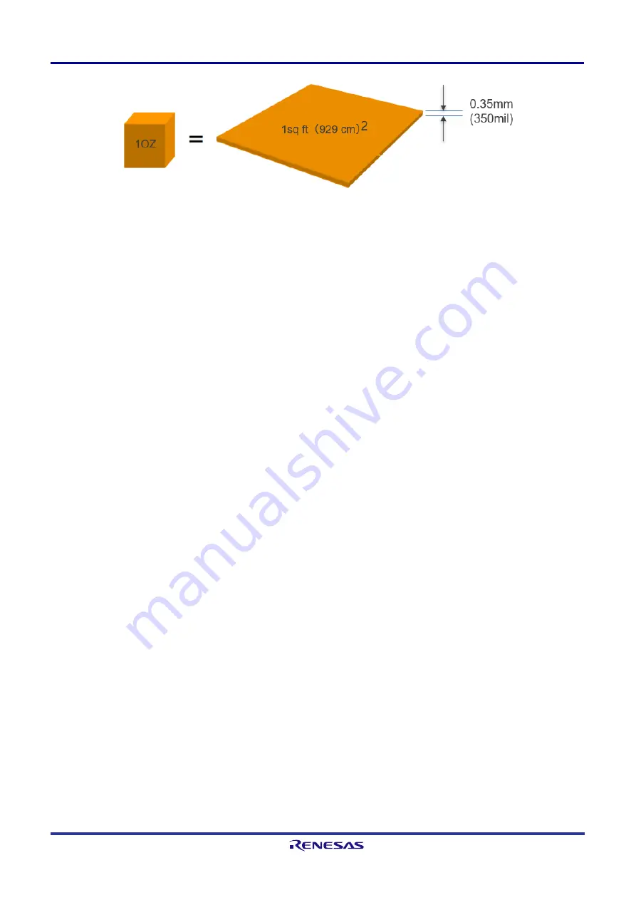
Figure 4. Copper Weight (Foil Thickness)
2. Placement
The optimal placement of the VC7 device and its neighboring components is specific to each design. The
following general recommendations are provided for the designer to consider:
■
Place the VC7 device/crystal away from switching power supply circuit.
■
Place and orient the VC7 device for convenient routing of input and output clock traces.
■
For crystal placement and routing recommendations, see “Crystal Placement and Handling”.
■
For decoupling capacitor placement and routing recommendations, see “Power Supply Trace and Power
Filtering Layout”.
3. Crystal Placement and Handling
Xin/Xout are the crystal oscillator circuit interface pins. Consider the following recommendations when using a
crystal:
■
Place the crystal as close to the IC pins as possible to minimize Xin/Xout trace length. The purpose of doing
so is to minimize parasitic capacitance and interference. For the same reason, avoid using vias in Xin/Xout
traces.
■
When using capacitors on each crystal pin to set the load capacitance value, connect the ground side of the
two capacitors close together and close to the IC ground connection. The reason is to minimize noise coupling
from the ground plane. The VC7 devices have internal capacitors. It is preferred to use internal capacitance to
avoid using external capacitors. When doing so, configure the internal capacitance based on crystal’s load
capacitance (CL) in the spec. Avoid overloading or underloading the crystal.
■
Treat the crystal component area as a “keep out area” for signal routing on other layers.
■
Rout Xin and Xout traces as non-coupled high impedance traces. Separate them by at least 3x the trace
width.
■
Xin can be overdriven by a single-ended LVCMOS signal, or an AC-coupled signal lead from a differential
pair, provided that the signal amplitude remain between 500mV and 1.2V and a slew rate of at least 0.2V/ns.
In this case, the VC7’s internal capacitance should be configured to a minimum value. In the following
schematics, place the signal termination resistor close to Xin pin.


