RZ/A2M CPU Board RTK7921053C00000BE
3. Operation specifications
R20UT4397EJ0100 Rev.1.00
3-13
2018.10.11
3.2.1
Jumpers (JP1 - JP3)
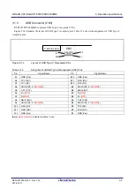
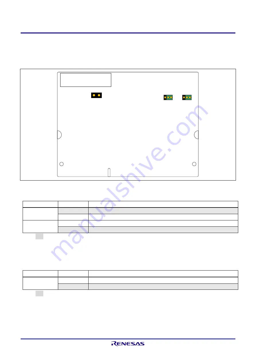
RTK7921053C00000BE contains three system setting jumpers.
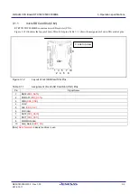
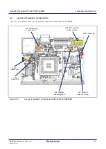
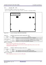
Figure 3.2.2 illustrates the layout of these jumpers. Table 3.2.1 and Table 3.2.2 lists jumper settings.
Figure 3.2.2
Layout of Jumpers of RTK7921053C00000BE
Table 3.2.1
Setting for Power Source Selection Jumpers (JP1, JP2)
Jumper
Setting
Function
JP1
ROMVcc selection
1
-
2
Supplies 3.3 V to PVcc_SPI and serial flash memory of RZ/A2M.
2
-
3
Supplies 1.8 V to PVcc_SPI and serial flash memory of RZ/A2M. (Setting prohibited)
JP2
RAMVcc selection
1
-
2
Supplies 3.3 V to PVcc_HO and HyperMCP of RZ/A2M. (Setting prohibited)
2
-
3
Supplies 1.8 V to PVcc_HO and HyperMCP of RZ/A2M.
[Note] : Initial setting
Before changing jumper settings, be sure to turn off the board.
If the jumper JP1 or JP2 are erroneously set, the memory may be damaged. Please confirm the pin number
closely when changing the settings.
Table 3.2.2
Settings for VBUS Power Supply Jumper (JP3)
Jumper
Setting
Function
JP3
For USB ch0
Short
Uses USB ch0 as host mode (with VBUS voltage supplied).
Open
Uses USB ch0 as function mode (with no VBUS voltage supplied).
[Note] : Initial setting.
Before changing jumper settings, be sure to turn off the board.
C side top view
JP3
2
1
3
JP2
3
1
JP1
1

