background image

RH850/U2A 292pin 

7. Connectors 

R20UT4970ED0101  Rev.1.01 

Page 42 of 67 

July 08, 2022 

7.2 

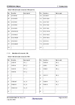
Debug Connector CN4 


Table 7.4 On-chip debug connector CN4 

Pin 

Function 

Device port 


Pin 

Function 

Device port 

TDCK / LPDCLK / 
FPCK 

JP0_2 


GND 

TRSTZ 


FLMD0 

TDO / LPDO / FPDT 

JP0_1 


TDI / LPDIO / FPDR 

JP0_0 


E0VCC 

TMS 

JP0_3 


10 


11 

RDY / LPDCLKOUT 

JP0_5 


12 

GND 

13 

RESETZ 


14 

GND 


7.3 

RHSIF/MSIP Connector CN5 


Table 7.5 RHSIF/MISP connector CN5 cont'd 

Pin 

JP1[2-1] 

JP1[2-3] 

Device port 

Function 

Device port 

Function 

P2_13 

HSIF0_TXDP / MSPI0_SOP 

P2_11 

HSIF0_RXDP / MSPI0_SIP 

P2_15 

MSPI0_SCKP 

P2_15 

MSPI0_SCKP 

P2_12 

HSIF0_TXDN / MSPI0_SON 

P2_10 

HSIF0_RXDN / MSPI0_SIN 

P2_14 

MSPI0_SCKN 

P2_14 

MSPI0_SCKN 


GND 


GND 

P2_9 

HSIF0_REFCLK / MSPI0CSS4 

P2_9 

HSIF0_REFCLK / MSPI0CSS4 

P2_11 

HSIF0_RXDP / MSPI0_SIP 

P2_13 

HSIF0_TXDP / MSPI0_SOP 


GND 


GND 

P2_10 

HSIF0_RXDN / MSPI0_SIN 

P2_12 

HSIF0_TXDN / MSPI0_SON 

10 


GND 


GND 

11 


GND 


GND 

12 


GND 


GND 

Summary of Contents for RH850 Series

Page 1: ...st information published by Renesas Electronics Corp through various means including the Renesas Electronics Corp website https www renesas com Y RH850 U2A 292PIN PB T1 V2 RH850 U2A 292pin User s Manual Piggyback Board www renesas com www renesas com www renesas com Rev 1 01 July 08 2022 User s Manual 32 RH850 Evaluation Platform The newest version of this document can be obtained from the followi...

Page 2: ...MPLIED WITH RESPECT TO THIS DOCUMENT AND ANY RELATED OR ACCOMPANYING SOFTWARE OR HARDWARE INCLUDING BUT NOT LIMITED TO THE IMPLIED WARRANTIES OF MERCHANTABILITY OR FITNESS FOR A PARTICULAR PURPOSE 8 When using Renesas Electronics products refer to the latest product information data sheets user s manuals application notes General Notes for Handling and Using Semiconductor Devices in the reliabilit...

Page 3: ...put signal during power off state as described in your product documentation 4 Handling of unused pins Handle unused pins in accordance with the directions given under handling of unused pins in the manual The input pins of CMOS products are generally in the high impedance state In operation with an unused pin in the open circuit state extra electromagnetic noise is induced in the vicinity of the ...

Page 4: ...e Voltage VDD Selection 24 3 4 Current Measurement Bridges 24 3 5 Power Supply LEDs 25 4 Clock Supply 26 4 1 Main Oscillator 26 4 2 Programmable Oscillator 27 4 3 X1 and X2 on CN15 27 5 Debug and Flash Programming Interfaces 28 6 Other Circuitry 29 6 1 Operation Mode Selection 29 6 2 RESET Switch 30 6 3 Signaling LEDs 30 6 4 Pull Up Pull Down Pin Header 30 6 5 Automotive Ethernet Interface 31 6 6 ...

Page 5: ... Supply by Debugger 50 8 2 Configuration Examples 51 8 2 1 General Settings 51 8 2 2 Jumper Indicators 51 8 2 3 Stand Alone Operation with Single External Power Supply Minimum Configuration 52 8 2 4 Stand Alone Operation with All External Power Supplies Maximum Configuration 53 8 2 5 Operation on the Main Board No External Supply 54 9 Precautions 55 9 1 Power Off Sequence 55 9 2 CAN0RX is Shared w...

Page 6: ...abbreviations are used H level L level high or low signal level of a digital signal the absolute voltage value depends on the signal 1 1 Package Components The Y RH850 U2A 292PIN PB T1 V2 product package consists of the following items After you have unpacked the box check if your Y RH850 U2A 292PIN PB T1 V2 package contains all of these items Table 1 1 Package Components for the Y RH850 U2A 292PI...

Page 7: ...1 Y RH850 X1X MB T2 Vx Y RH850 X2X MB T1 V1 1 3 Main Features Burn in socket for mounting of the device Several power set up options Combined operation with powering from main board Stand alone operation with single power supply e g 3 3 V or 5 0 V only Stand alone operation with flexible individual power supply typ 1 12 V 3 3 V 5 0 V Refer to 3 3 Device Core Voltage VDD Selection for further detai...

Page 8: ...w R20UT4970ED0101 Rev 1 01 Page 8 of 67 July 08 2022 1 4 Piggyback Board Views Following figures provide the top and bottom views of the piggyback board Figure 1 2 Piggyback board bottom view Figure 1 1 Piggyback board top view ...

Page 9: ... Overview R20UT4970ED0101 Rev 1 01 Page 9 of 67 July 08 2022 Following figures provide the drawing of top and bottom views of the piggyback board Figure 1 4 PiggyBack Board bottom view Figure 1 3 PiggyBack Board top view ...

Page 10: ... see chapter 1 6 Modifications for U2A6 device The device must be placed inside the socket IC1 To insert the device align the device package A1 pin with the marking of the socket The A1pin of the socket is marked with a circle near to the IC1 label see also white point in Figure 1 1 Piggyback board top view The A1 pin of the device is marked by a white triangle on the package see white circle in t...

Page 11: ...RX_DATA_N VSS RB1 H16 TX_DATA_P E0VCC RB3 J16 TX_DATA_N E0VCC RB3 K16 GETH0BVCC E0VCC JP2 G17 GETH0PVCC E0VCC JP3 H17 GETH0RVCC E0VCC JP22 E17 GETH0VCL VSS RB5 The jumpers JP2 JP3 and JP22 must have the same setting as JP6 E0VCC The four 0R resistors RB1 RB4 are on the upper side of the pcb The setting of RB1 RB4 for U2A16 8 or U2A6 use is printed on the pcb Fig 1 6 On the lower side of the pcb th...

Page 12: ... TX_DATA_N Decoupling capacitors C41 and C44 Placed between Ethernet transceiver and bridges RB3 RB4 Placed between RH850 U2A and bridges RB3 RB4 Decoupling capacitors C41 C44 C47 C48 Value 100nF Value 4 7nF Resistor R34 Uses 100 Ohm resistor to connect RX_DATA_N and RX_DATA_P The pcb provides soldering points to add a resistor between RX_DATA_N and RX_DATA_P but by default this resistor is not fi...

Page 13: ... This section provides complete lists of all jumpers connectors and LEDs The placement of these components on the board is depicted in the figure below 2 1 Jumpers Overview The following table provides an overview of all jumpers Figure 2 1 Placement of jumpers connectors and LEDs Figure 2 2 Placement of connectors on bottom side ...

Page 14: ...C must be same as JP6 JP2 2 1 5 0 V JP2 2 3 3 3 V refer to 3 2 Voltage Distribution JP3 For processor U2A16 Voltage selection for GETH0PVCC JP3 2 3 3 3 V For processor U2A8 6 Voltage selection for E0VCC must be same as JP6 JP3 2 1 5 0 V JP3 2 3 3 3 V refer to 3 2 Voltage Distribution JP4 Current measurement bridge of 5 0 V power rail refer to 3 4 Current Measurement Bridges JP5 Current measurement...

Page 15: ...ution JP12 Voltage selection for SVRDRVCC JP12 2 1 5 0 V JP12 2 3 3 3 V refer to 3 2 Voltage Distribution JP13 Voltage selection for SVRAVCC JP13 2 1 5 0 V JP13 2 3 3 3 V refer to 3 2 Voltage Distribution JP14 Voltage selection for VDDIOF JP14 2 1 5 0 V JP14 2 3 3 3 V refer to 3 2 Voltage Distribution JP15 Voltage selection for Pull up Pull down pin header CN12 pins 11 13 15 17 19 JP15 2 1 5 0 V J...

Page 16: ...2 2 1 5 0 V JP22 2 3 3 3 V For processor U2A8 6 Voltage selection for E0VCC must be same as JP6 JP22 2 1 5 0 V JP22 2 3 3 3 V refer to 3 2 Voltage Distribution JP23 Voltage selection for VDD JP23 2 1 VDDs JP23 2 3 SVR_OUTPUT refer to 3 3 Device Core Voltage VDD Selection JP25 Voltage selection for Pull up Pull down pin header CN12 pins 1 3 5 7 9 JP25 2 1 5 0 V JP25 2 3 3 3 V refer to 6 4 Pull Up P...

Page 17: ... to 3 2 Voltage Distribution JP35 Voltage selection for A1VREFH JP35 2 1 5 0 V JP35 2 3 3 3 V refer to 3 2 Voltage Distribution JP36 Voltage selection for A2VCC JP36 2 1 5 0 V JP36 2 3 3 3 V refer to 3 2 Voltage Distribution JP37 Voltage selection for A2VREFH JP37 2 1 5 0 V JP37 2 3 3 3 V refer to 3 2 Voltage Distribution JP38 MODE0 level selection JP38 2 1 H level JP38 2 3 L level refer to 6 1 Op...

Page 18: ...erview cont d Jumper Function Remark JP41 FLMD0 level selection JP41 2 1 H level JP41 OPEN if no debug programming tool connected L level controlled by debug programming tool if tool connected refer to 6 1 Operation Mode Selection Note Refer to 3 3 Device Core Voltage VDD Selection for further details about VDD voltage ...

Page 19: ... to 6 5 Automotive Ethernet Interface and 7 6 Ethernet Connector CN6 and CN17 CN7 Signaling LEDs pin header refer to 6 3 Signaling LEDs CN8 GND for external power supply refer to 3 1 Board Power Connection connectors are not assembled on the board CN9 5 0 V external power supply CN10 3 3 V external power supply CN11 1 12 V external power supply CN12 Pull up Pull down pin header refer to 6 4 Pull U...

Page 20: ...ed LED2 Signaling LED yellow connection via CN7 refer to 6 3 Signaling LEDs LED3 Signaling LED LED4 Signaling LED LED5 Signaling LED LED6 Signaling LED LED7 Signaling LED LED8 Signaling LED LED9 Signaling LED LED10 1 12 V device core voltage VDD green refer to 3 5 Power Supply LEDs LED11 5 0 V power supply P5V0 green LED12 3 3 V power supply P3V3 green LED13 Reset switch SW1 on red LED14 Device VM...

Page 21: ...able to supply external voltages Four 4 mm banana type connectors are used to connect external power supplies black connector CN8 for GND VSS red connector CN9 for 5 V red connector CN10 for 3 3 V red connector CN11 for 1 12 V Refer to 3 3 Device Core Voltage VDD Selection for further details about VDD voltage These connectors are not assembled at delivery of the board but separately supplied with...

Page 22: ... on chip flash memory SVRDRVCC 3 3 V 5 V Power supply for on chip Switching Voltage Regulator SVR SVRAVCC 3 3 V 5 V VDDIOF 3 3 V 5 V I O voltage supply for the Main Board GETH0PVCC 3 3 V 5V Power supply for Ethernet domain for U2A16 only GETH0BVCC 3 3 V 5V GETH0RVCC 3 3 V 5V A0VCC A1VCC A2VCC 3 3 V 5 V A D Converter s power supplies and reference voltages A0VREFH A1VREFH A2VREFH 3 3 V 5 V VDD 1 12...

Page 23: ... 0V 5V0 3 3V or 5V 1u E2VCC 3 3V or 5V 1u 1u A2VREFH 1u 3 3V or 5V 3 3V or 5V 3 3V or 5V 3 3V or 5V 3 3V or 5V 1u 1u A2VCC A1VREFH A1VCC A0VREFH P5V0 A5V0 A3V3 P3V3 1u 1u 1u 3 3V 5 0V 5 0V 3 3V JP33 JP36 JP35 C104 JP22 JP2 C107 JP3 JP14 C109 C108 C106 C105 JP37 JP34 JP32 JP31 JP30 JP13 JP12 JP11 JP10 JP9 JP8 JP7 JP6 JP5 JP4 C94 C95 C96 3 2 1 3 2 1 3 2 1 3 2 1 3 2 1 3 2 1 3 2 1 3 2 1 3 2 1 3 2 1 2 ...

Page 24: ...nd JP16 JP23 2 1 VDD 1 12 V VDDs from JP16 2 1 VDDs reg_vcc_VDD from on board voltage regulator IC16 JP16 2 3 VDDs IN_1v12 from external supply CN11 JP23 2 3 VDD 1 09 V SVR_OUTPUT Note If JP23 2 3 VDD 1 09 V SVR_OUTPUT is selected as core voltage it is not possible to operate the device in DeepSTOP mode Please refer to the precaution in 9 3 DeepSTOP Mode when using SVR for details 3 4 Current Meas...

Page 25: ...ev 1 01 Page 25 of 67 July 08 2022 3 5 Power Supply LEDs The following green LEDs indicate the presence of various voltages on the piggyback board LED11 for 5 0 V power rail P5V0 LED12 for 3 3 V power rail P3V3 LED10 for 1 12 V device core voltage VDD ...

Page 26: ...r to the figure above Several resonators for various main oscillator frequencies 16 MHz 20 MHz 24 MHz 40 MHz are included in the board package The 40MHz resonator is by default mounted to X1 For package content please refer to 1 1 Package Components CAUTION Only one oscillator either X1 or X3 can be used at any one time for the main oscillator 20 MHz provide additional 24 MHz provide additional 16...

Page 27: ...erminal via resistor R2 The SG 8002CE is neither mounted on nor provided with the board For details about the available circuitry refer to Figure 4 1 Clock supply CAUTION A resonator mounted on socket X1 or soldered on X3 must not be used in parallel to another clock source 4 3 X1 and X2 on CN15 To minimize disturbance on the resonator signal the signals X1 and X2 are by default not connected to a...

Page 28: ...mming Interfaces For debugging and flash programming purposes debug and flash programming tools can be connected to the CN4 connector Refer to 7 2 Debug Connector CN4 for details about the CN4 pin assignment The Renesas standard emulator for RH850 U2A is the E2 emulator This can be used as emulator for debugging or as flash programmer ...

Page 29: ...1 H level JP39 OPEN FLMD1 GND JP40 FLMD2 pin level JP40 2 1 FLMD2 H level JP40 2 3 FLMD2 GND CAUTION Be careful in configuration of the operation mode related pins The wrong configuration and operation of the device outside of its specification can cause irregular behavior of the device and long term damage cannot be excluded Be sure to check the corresponding Hardware User s Manual for details wh...

Page 30: ...N Note LED13 does not light up when RESET is asserted by any other means than SW1 6 3 Signaling LEDs Eight LEDs are provided to allow visual observation of the output state of device port pins Device pins AP2_8 to AP2_15 are connected to the odd pins of the pin header CN7 while the LEDs 2 to 9 are connected to the even CN7 pins Thus the LEDs can be either connected to the device port pins Ap2_8 to...

Page 31: ...l Down Pin Header CN12 for CN12 details 6 5 Automotive Ethernet Interface The piggyback board features a Marvell 88Q2112 Automotive Ethernet PHY IC2 for using the device s SGMII interface ETNB1 via the TE MateNet connector on CN17 or straight wires on block connector CN6 If the TE MateNet connector should be used connector CN17 has to be assembled with the connector included in the delivery Please...

Page 32: ...Internal MOSC clock of 20MHz For an internal MOSC clock of 20MHz the crystal X1 has to be replaced by the 20MHz crystal included in the package For package content please refer to Table 1 1 Package Components for the Y RH850 U2A 292PIN PB T1 V2 2 The signals of the device s Fast Ethernet R MII interface ETNB0 are available on the Main Board connectors Thus ETNB0 can control an Ethernet PHY on the ...

Page 33: ...nterface at CN5 are operated in LVDS mode Rx and Tx signals available at CN5 can be swapped by setting the jumper JP1 JP1 2 1 RXDP RXDN at CN5 pins 7 and 9 TXDP TXDN at CN5 pins 1 and 3 JP1 2 3 RXDP RXDN at CN5 pins 1 and 3 TXDP TXDN at CN5 pins 7 and 9 Notes 1 In order to minimize signal interference no signals from CN5 are connected to CN16 If required they can be connected via 0 Ω resistors R15...

Page 34: ...n Boards for a list of supported Main Boards 7 1 1 Main Board Connector CN1 Table 7 1 Main board connector CN1 cont d Pin Main Board function Piggyback board device port Pin Main Board function Piggyback board device port 1 VDDA 2 VDDA 3 VDDA 4 VDDA 5 RESET RESETZ 6 NMI P4_7 7 WAKE 8 9 INT0 P10_12 10 INT1 P22_0 11 INT2 P21_7 12 INT3 P2_8 13 14 15 UART0TX P6_6 16 UART1TX P6_3 17 UART0RX P6_5 18 UAR...

Page 35: ...TX P20_7 42 FLX0EN P20_5 43 FLX0RX P20_2 44 FLXSTPWT P20_4 45 FLX1TX P20_6 46 FLX1EN P20_8 47 FLX1RX P20_3 48 FLX CLK P10_8 49 50 51 ETH0MDIO P20_3 52 ETH0MDC P20_6 53 ETH0RXD0 P10_3 54 ETH0TXD0 P20_9 55 ETH0RXD1 P10_4 56 ETH0TXD1 P20_10 57 ETH0RXD2 P10_5 58 ETH0TXD2 P20_12 59 ETH0RXD3 P10_6 60 ETH0TXD3 P20_13 61 ETH0RXCLK P10_2 62 ETH0TXCLK P10_1 63 ETH0RXER P10_0 64 ETH0TXER P20_8 65 ETH0CRSDV P...

Page 36: ...GIO_2 P21_4 88 DIGIO_3 P21_5 89 DIGIO_4 P21_6 90 DIGIO_5 P21_7 91 DIGIO_6 P22_0 92 DIGIO_7 P22_1 93 DIGIO_8 P22_2 94 DIGIO_9 P22_3 95 DIGIO_10 P10_8 96 DIGIO_11 P10_9 97 DIGIO_12 P10_10 98 DIGIO_13 P10_11 99 DIGIO_14 P10_12 100 DIGIO_15 P10_13 101 102 103 MUX0 P6_0 104 MUX1 P6_2 105 MUX2 P6_3 106 107 ADC0 AP4_0 108 ADC1 AP4_1 109 ADC2 AP4_2 110 ADC3 AP4_3 111 ADC4 AP4_4 112 ADC5 AP3_1 113 ADC6 AP3...

Page 37: ...4_14 11 LIN2RX P2_1 12 LIN3RX P4_15 13 LIN4TX P6_12 14 LIN5TX P2_2 15 LIN4RX P6_15 16 LIN5RX P2_3 17 LIN6TX P2_7 18 LIN7TX P3_5 19 LIN6RX P2_6 20 LIN7RX P3_4 21 LIN8TX P4_0 22 LIN9TX P5_3 23 LIN8RX P4_1 24 LIN9RX P5_2 25 LIN10TX P6_5 26 LIN11TX P3_8 27 LIN10RX P6_4 28 LIN11RX P3_7 29 LIN12TX 30 LIN13TX 31 LIN12RX 32 LIN13RX 33 LIN14TX 34 LIN15TX 35 LIN14RX 36 LIN15RX 37 38 39 CAN12TX P24_10 40 CAN...

Page 38: ..._7 58 CAN11RX P24_9 59 60 61 LIN16TX 62 LIN17TX 63 LIN16RX 64 LIN17RX 65 LIN18TX 66 LIN19TX 67 LIN18RX 68 LIN19RX 69 LIN20TX 70 LIN21TX 71 LIN20RX 72 LIN21RX 73 LIN22TX 74 LIN23TX 75 LIN22RX 76 LIN23RX 77 78 79 SFMA0CLK P17_5 80 SFMA0SSL P17_4 81 SFMA0IO0 P17_3 82 SFMA0IO1 P17_2 83 SFMA0IO2 P17_1 84 SFMA0IO3 P17_0 85 86 87 MMCA0CLK P24_4 88 MMCA0CMD P24_5 89 MMCA0DAT0 P24_6 90 MMCA0DAT1 P24_7 91 M...

Page 39: ...XD3 109 ETH1RXCLK 110 ETH1TXCLK 111 ETH1RXER 112 ETH1TXER 113 ETH1CRSDV 114 ETH1TXEN 115 ETH1RXDV 116 ETH1COL 117 ETH1RESET 118 ETH1LINK 119 120 7 1 3 Main Board Connector CN3 Table 7 3 Main board connector CN3 cont d Pin Function Device port Pin Function Device port 1 CSI0CS0 P21_7 2 CSI0CLK P22_4 3 CSI0CS1 P21_6 4 CSI0SI P22_1 5 CSI0CS2 P21_5 6 CSI0SO P22_0 7 CSI0CS3 P21_4 8 9 10 CSI1CS1 P24_8 1...

Page 40: ...P4_8 23 24 CSI1CS0 P24_7 25 26 DIGIO_24 P17_6 27 28 CSI1SO P24_6 29 CSI1SCLK P24_4 30 CSI1SI P24_5 31 32 33 34 35 36 37 38 39 40 41 42 43 44 45 46 47 48 49 50 51 52 53 54 55 AD1_0 AP2_0 56 AD1_1 AP2_1 57 AD1_2 AP2_2 58 AD1_3 AP2_3 59 AD1_4 AP2_4 60 AD1_5 AP2_5 61 AD1_6 AP2_6 62 AD1_7 AP2_7 63 PWM0 P24_4 64 PWM1 P24_5 65 PWM2 P24_6 66 PWM3 P24_7 67 PWM4 P24_8 68 PWM5 P24_9 69 PWM6 P24_10 70 PWM7 P2...

Page 41: ...evice port Pin Function Device port 71 DIGIO16 AP0_0 72 DIGIO17 AP0_1 73 DIGIO18 AP0_2 74 DIGIO19 AP0_3 75 DIGIO20 AP0_4 76 DIGIO21 AP0_5 77 DIGIO22 AP0_6 78 DIGIO23 AP0_7 79 ENC0 P10_8 80 ENC1 P10_9 81 82 83 84 85 86 87 88 89 90 91 92 93 94 95 96 97 98 99 100 101 102 103 104 105 106 107 108 109 110 111 112 113 114 115 116 117 118 119 120 ...

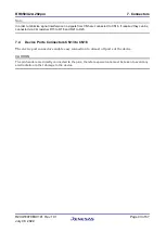
Page 42: ...TZ 14 GND 7 3 RHSIF MSIP Connector CN5 Table 7 5 RHSIF MISP connector CN5 cont d Pin JP1 2 1 JP1 2 3 Device port Function Device port Function 1 P2_13 HSIF0_TXDP MSPI0_SOP P2_11 HSIF0_RXDP MSPI0_SIP 2 P2_15 MSPI0_SCKP P2_15 MSPI0_SCKP 3 P2_12 HSIF0_TXDN MSPI0_SON P2_10 HSIF0_RXDN MSPI0_SIN 4 P2_14 MSPI0_SCKN P2_14 MSPI0_SCKN 5 GND GND 6 P2_9 HSIF0_REFCLK MSPI0CSS4 P2_9 HSIF0_REFCLK MSPI0CSS4 7 P2_...

Page 43: ...to CN16 If required they can be connected via 0 Ω resistors R15 to R18 and R21 to R23 7 4 Device Ports Connectors CN13 to CN16 The device port connectors enable easy connection to almost all ports of the device CAUTION The pin headers are directly connected to the pins therefore special care must be taken to avoid any electrostatic or other damage to the device ...

Page 44: ...AP0_6 4 AP0_2 5 AP0_8 6 AP1_3 7 AP0_1 8 AP1_2 9 AP0_3 10 AP1_1 11 AP0_5 12 AP1_0 13 AP0_7 14 AP0_15 15 AP0_13 16 AP0_14 17 AP0_9 18 AP0_12 19 AP0_11 20 AP0_10 21 P3_3 22 P3_2 23 P24_5 24 P24_4 25 P24_6 26 P24_7 27 P24_8 28 P24_9 29 P24_10 30 P24_11 31 P24_13 32 P24_12 33 P4_1 34 P4_0 35 P4_5 36 P4_4 37 P4_7 38 P4_6 39 P4_9 40 P4_8 41 P4_11 42 P4_10 43 P4_13 44 P4_12 ...

Page 45: ..._0 2 P10_1 3 P10_2 4 P10_3 5 P10_4 6 P10_5 7 P10_6 8 P10_7 9 P10_8 10 P10_9 11 P10_10 12 P10_11 13 P10_12 14 P10_13 15 P10_14 16 P21_6 17 P17_0 18 P21_7 19 P17_1 20 P17_2 21 P17_3 22 P17_4 23 P17_5 24 P17_6 25 AP2_10 26 AP2_13 27 AP2_8 28 AP2_14 29 AP2_6 30 AP2_11 31 AP2_4 32 AP2_15 33 AP2_2 34 AP2_7 35 AP2_9 36 AP3_0 37 AP2_5 38 AP3_2 39 AP2_3 40 AP3_3 41 AP2_1 42 AP3_1 43 AP2_0 44 AP2_12 ...

Page 46: ... P6_4 11 P6_3 12 P6_6 13 P6_5 14 P6_8 15 P6_7 16 P6_12 17 P6_9 18 P6_10 19 P6_15 20 P6_14 21 P6_13 22 P6_0 23 P3_4 24 P3_5 25 P3_7 26 P3_6 27 JP0_3 28 P3_8 29 JP0_1 30 JP0_5 31 JP0_0 32 JP0_2 33 TRSTZ 34 GETH0VCL 35 FLMD0 36 RESETZ 37 VMONOUTZ 38 PWRCTL 39 X2_C 40 X1_C 41 P5_2 42 P5_3 43 P5_4 44 P5_6 Note By default these signals are not connected to CN15 in order to minimize signal interference I...

Page 47: ..._P2_11 14 CN_P2_10 15 CN_P2_13 16 CN_P2_12 17 CN_P2_15 18 CN_P2_14 19 P22_4 20 P22_3 21 P22_2 22 P22_1 23 P20_0 24 P22_0 25 P20_2 26 P20_1 27 P20_4 28 P20_3 29 P20_6 30 P20_5 31 P20_8 32 P20_7 33 P20_10 34 P20_9 35 P21_1 36 P21_0 37 P21_3 38 P21_2 39 P21_4 40 P20_13 41 P21_5 42 P20_12 43 ERROROUTZ 44 P20_14 Note By default these signals are not connected to CN16 in order to minimize signal interfe...

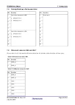
Page 48: ...fixed L level 3 4 5 6 7 8 9 10 11 fixed H level depends on JP15 JP15 2 1 5 0 V JP15 2 3 3 3 V 12 13 14 15 16 17 18 19 20 7 6 Ethernet Connector CN6 and CN17 Please refer to 6 5 Automotive Ethernet Interface for details on the function of these pins Table 7 9 Ethernet connector CN6 Pin Function 1 MDIN_cn 2 MDIP_cn Table 7 10 Ethernet connector CN17 Pin Function 1 MDIN_cn 2 MDIP_cn 3 GND 4 GND 5 GND...

Page 49: ...r CN20 Please refer to the data sheet of Marvell 88Q2112 Automotive 100 1000BASE T1 Transceiver for details on the function of these pins Table 7 11 GPIO LED connector CN20 Pin JP1 2 1 Device port Function 1 GPIO pin 42 GPIO output of Marvell PHY 2 NC Not connected 3 LED pin 41 LED output of Marvell PHY ...

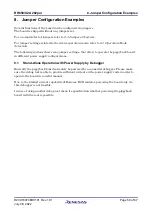
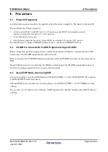
Page 50: ... some jumper settings that allow to operate the piggyback board in different power supply configurations 8 1 Stand Alone Operation with Power Supply by Debugger Basically the piggyback board can solely be powered by a connected debugger Please make sure the debug tool is able to provide sufficient current on the power supply rails in order to operate the board in a useful manner Due to the limited...

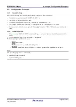
Page 51: ...coming with the board are plugged into X1 socket For connection to external power supplies the banana type connectors CN8 to CN11 must be assembled on the board 8 2 2 Jumper Indicators The green jumper JP41 for FLMDO0 must always be open for a normal user mode and debug operation of the device The red jumpers are related to the power supply configuration Following jumper symbols are used open jump...

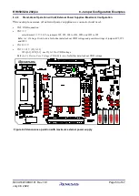
Page 52: ...an only use 3 3 V CN8 GND connection CN9 not connected no 5 0 V jumpers JP2 JP3 JP6 to JP14 JP22 and JP32 to JP37 are set to 3 3 V position 2 3 CN10 3 3 V CN11 not connected no IN_1v12 JP16 2 1 use reg_vcc_VDD from on board voltage regulator for supply of VDD voltage VDD from reg_vcc_VDD JP23 2 1 or from SVR_OUTPUT JP23 2 3 from on chip Switching Voltage Regulator Refer to 3 3 Device Core Voltage ...

Page 53: ...CN8 GND connection CN9 5 V select desired 3 3 V 5 0 V via jumpers JP2 JP3 JP6 to JP14 JP22 and JP32 to JP3 Refer to 3 2Voltage Distribution for further details about VDD voltage and possible settings of jumpers JP2 JP3 and JP22 CN10 3 3 V CN11 1 12 V IN_1v12 JP16 2 3 JP23 2 1 use IN_1v12 for VDD voltage Refer to 3 3 Device Core Voltage VDD Selection for further details about VDD voltage Figure 8 2...

Page 54: ...her details about VDD voltage and possible settings of jumpers JP2 JP3 and JP22 VDD supply JP16 2 1 use reg_vcc_VDD from on board voltage regulator for supply of VDD voltage VDD from reg_vcc_VDD JP23 2 1 or SVR_OUTPUT JP23 2 3 from on chip Switching Voltage Regulator Refer to 3 3 Device Core Voltage VDD Selection for further details about VDD voltage Note This configuration still allows to utilize...

Page 55: ... 2 RESET Switch 9 2 CAN0RX is Shared with FLASH Programmer Signal FLMD1 When using this product plugged into a motherboard where CAN0 is connected to the CAN transceiver the FLASH programmer will not work This is because the CAN0RX function is shared with the FLMD1 function on the same device PIN Most CAN transceiver are driving the RX line actively and the FLASH programmer then is not able to cha...

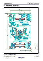
Page 56: ...RH850 U2A 292pin 10 Mechanical Dimensions R20UT4970ED0101 Rev 1 01 Page 56 of 67 July 08 2022 10 Mechanical Dimensions Figure 9 1 Mechanical dimensions ...

Page 57: ...ard upon delivery Oscillators and resonators OSC1 X3 Capacitors C60 C61 C97 C98 Resistors R2 R4 R6 R15 R18 R20 R21 R23 R25 R143 The above components are indicated with DNF DNB in the schematics The following components described in the schematics are provided with but not mounted on the board upon delivery 3 Hirschmann 4 mm power lab sockets red for CN9 CN11 1 Hirschmann 4 mm power lab sockets bla...

Page 58: ...3V or 5V 100n R1 C16 OSC1 R4 R2 R3 X1 TR1 L1 TR2 C14 C19 C36 C1 C3 C4 C6 C7 C9 C10 C37 C43 C56 C42 C50 C59 C62 C63 C64 R6 R7 C38 C39 C45 C12 TP10 TP9 TP4 C13 C5 C8 C97 C98 R143 C17 C18 C2 RB1 RB2 RB3 RB4 R34 X3 C68 C69 C20 C22 C23 C25 C26 C27 C28 C29 C21 C24 C31 C30 C44 C41 IC1 R58 R85 FS1 FS2 FS3 FS4 FS5 FS6 RB5 6C9 5B3 5C3 5B3 3E5 2D3 4A1 2D3 2D3 2C2 6D1 4C2 2D2 6A1 4C1 2D6 6B6 6B4 6B3 4E6 4E3 2...

Page 59: ...P2 6 AP2 4 AP2 2 AP2 9 P4 4 P4 0 P24 7 AP0 2 AP1 3 AP1 1 AP0 0 AP0 10 P24 11 P24 9 P24 4 P3 2 P24 12 P4 5 P4 1 P24 13 P24 10 P24 8 P24 6 P24 5 P3 3 AP0 9 AP0 7 AP0 5 AP0 3 AP0 1 AP0 8 AP0 6 AP0 4 P4 12 P4 10 P4 8 P4 6 P4 13 P4 11 P4 9 P4 7 P6 11 AP4 1 AP4 2 AP4 3 JP0 0 JP0 1 JP0 3 P3 7 P3 4 P6 13 P6 15 P6 9 P6 7 P6 5 P6 3 P6 2 P5 4 P5 2 P21 3 P21 1 P20 10 P20 8 P20 6 P20 4 P20 2 P20 0 P22 2 P22 4 ...

Page 60: ...TO DELIVER WITH THE BOARD 10K 56K 1K6 1u 1u 1u 1K0 1K0 1K0 1K0 1K0 1K0 1K0 1K0 1K0 header 20way 1K0 1K0 1K0 1K0 1K0 1K0 1K0 1K0 1K0 1K0 1K0 NXP_BC847C 10K 10K 10K NXP_BC847C BT1H 2M4 Z 10K TLC7701ID 10K SN74LV1T125DCKR 2K2 100U 100U 220n 750 750 3 3V 3 3V 3 3V red 3 3V green green 1 12V 5 0V 3 3V 5 0V 3 3V 5 0V 5 0V 3 3V 3 3V JP33 JP36 JP35 C104 JP22 JP2 C107 JP3 JP14 TR9 C155 C156 IC16 C81 JP23 J...

Page 61: ...3V3 SYSVCC E0VCC 3V3 BSS84 BSS84 BSS84 R48 LED15 R47 TR11 R19 C83 IC17 R5 R130 JP41 R122 R12 R119 LED14 TR10 TR3 R121 R124 JP38 R120 JP40 R123 JP39 LED9 R33 LED8 R32 LED7 R31 LED6 R30 LED5 R29 LED4 R28 LED3 R27 LED2 R26 C67 C66 R23 R22 R21 JP1 IC3 CN7 R11 R14 CN4 R8 LED1 R13 R9 CN5 R15 R16 R17 R18 6C4 6B4 2B2 6B1 6B7 6C7 2C6 1C9 4C6 1C7 2B3 6B6 6B9 6C6 1C7 2C8 2D6 2D8 4E6 6B3 6B4 6B6 1C3 2D3 3E5 6...

Page 62: ...5 JP20 JP17 JP18 CN20 C61 C60 CN6 C48 C47 R40 R39 R81 R80 R82 R38 JP19 C51 C52 C53 C57 C58 C54 C55 VA2 VA1 C35 C34 C33 C32 C40 R36 R37 R35 FC1 FIL1 C15 C11 R25 R20 R24 XTAL1 IC2 6B1 2D2 6B6 1C7 2D3 6B1 1C7 1C1 1C1 1C1 1C1 1C3 2A2 SIN SIP MDIN_cn MDIP_cn MDIN_c MDIP_c MDIP_f MDIN_f P3 7 P3 6 RESETN NC MDIP MDIN NC NC NC NC NC NC NC NC NC NC NC NC NC NC MDC MDIO NC NC NC NC NC XTAL_OUT XTAL_IN AP0 8...

Page 63: ...4 1C7 2B8 6B9 1C7 2B3 4A5 6B6 1C7 2B2 4A5 6B4 6C7 1C7 2B2 4A5 6B6 6B9 6C7 1C7 2B2 4A5 6B6 1C7 2B3 4A5 6B3 6B4 6B9 6C9 1C7 2B6 6B3 6C1 1C7 2B2 4A5 6B4 6C4 1C7 2B2 4A5 6B6 6B9 6C4 1C7 2B3 4A5 6B6 6B7 6C4 1C7 2B3 4A5 6B4 6C6 1C7 2B3 4A5 6B3 6B4 6B9 6C6 1C7 2B2 4A5 6B6 6B9 6C6 1C7 2B2 4A5 6B1 6B4 6B9 6C4 AP3 1 NC RESETZ P4 9 P4 8 P6 5 P6 6 NC P21 7 NC NC P24 9 AP0 5 Ap0 7 AP0 3 AP0 1 AP0 6 AP0 4 AP0 2...

Page 64: ... 54 Corrected jumper JP41 setting in Figure 8 1 Stand alone operation with minimum external power supply Figure 8 2 Stand alone operation with maximum external power supply and Figure 8 3 Main board operation without external power supply V1 00 2021 05 21 Initial release ...

Page 65: ...Colophon RH850 U2A 292pin Piggyback Board V2 User s Manual Piggyback Board Publication Date Rev 1 01 July 08 2022 Published by Renesas Electronics Corporation ...

Page 66: ... P R China Tel 86 21 2226 0888 Fax 86 21 2226 0999 Renesas Electronics Hong Kong Limited Unit 1601 1611 16 F Tower 2 Grand Century Place 193 Prince Edward Road West Mongkok Kowloon Hong Kong Tel 852 2265 6688 Fax 852 2886 9022 Renesas Electronics Taiwan Co Ltd 13F No 363 Fu Shing North Road Taipei 10543 Taiwan Tel 886 2 8175 9600 Fax 886 2 8175 9670 Renesas Electronics Singapore Pte Ltd 80 Bendeme...

Page 67: ...Back Cover RH850 U2A 292pin R20UT4970ED0101 ...

Reviews: