R01AN5644EJ0100 Rev.1.00
Page 6 of 62
Jan 22, 2021
Reference Guide for a 2-Axis Robot Arm with 2-Phase Stepping
Motors Incorporating Resolvers
RX24T, RX72M,
RAA3064002GFP/RAA3064003GFP
1. Specifications of the Demo System
This section describes the overall configuration of the demo system and the specifications of each of the
modules.
1.1 Overall Configuration of the Demo System
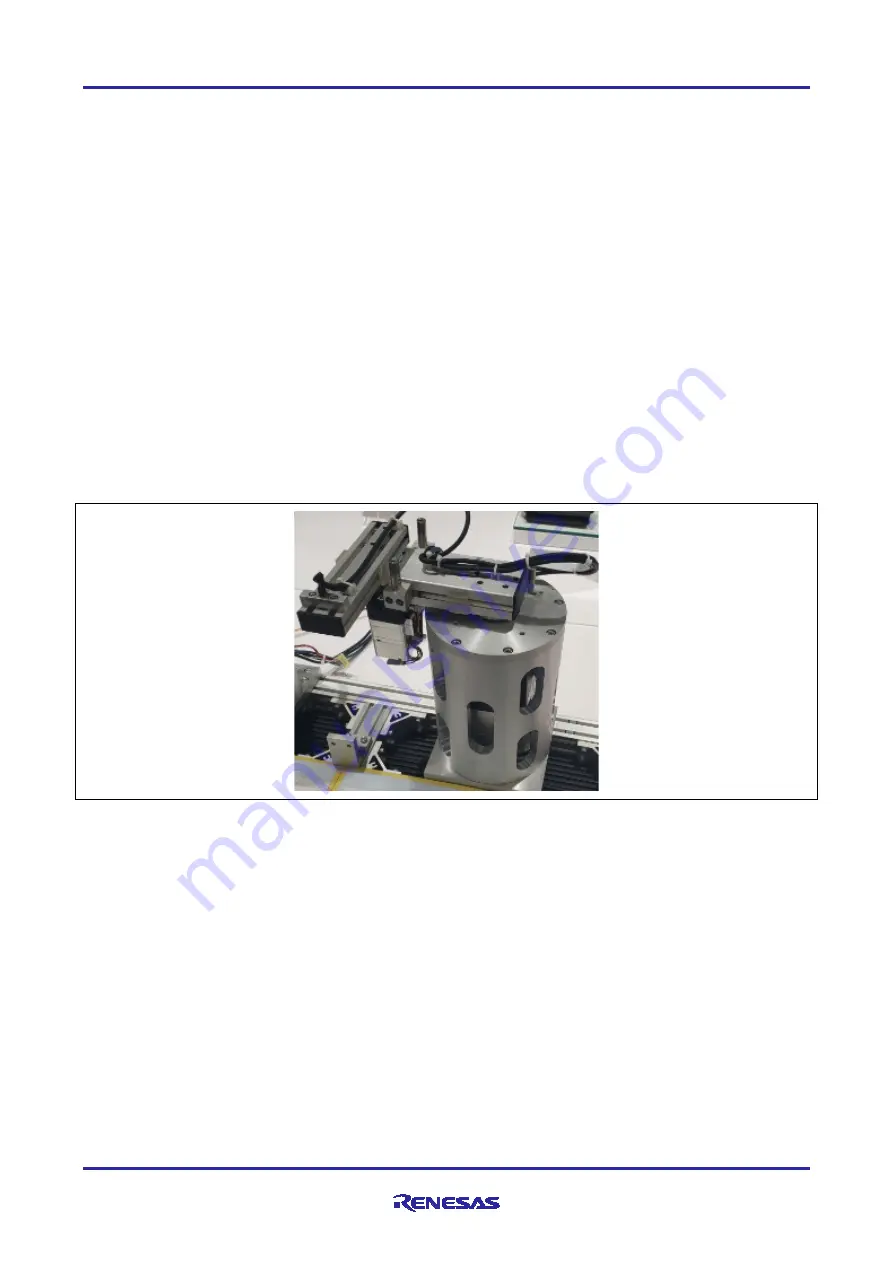
Figure 1-1 shows the external appearance of the demo system, Figure 1-2 is a system configuration
diagram, and Figure 1-3 shows a schematic view of controlling the demo system. Table 1-1 lists the
components of the demo system.
The 85-mm square motor is housed in a cylindrical case and connected to arm 1, and the 42-mm square
motor and arm 2, which operates in accordance with the rotation of the 42-mm square motor, are connected
to the tip of arm 1. A laser module is attached to the tip of arm 2 and the laser light produces illumination in
the direction of the ground. The 42-mm square board and 85-mm square board are installed for the 42-mm
square motor and 85-mm square motor in respective integral structures, and each of the motors rotates to
operate the arms upon receiving control instructions from the NC board, which is connected to the control
boards via RS-485 links. Origin sensors for detecting the origin positions of arm 1 and arm 2 are attached to
arm 1 and the cylindrical case, and the signals from the origin sensors are connected to the 42-mm square
board and 85-mm square board. The system control board is connected to a PC by a USB cable, and control
instructions for the motors are generated from operation commands generated with a GUI on the PC. The
42-mm square board and 85-mm square board are driven by a 24-V power supply and the NC board is
driven by a 5-V power supply. A 3-V power supply generated on the NC board is supplied to the laser
module.
Figure 1-1 External Appearance of the Demo System


