background image

14

2.5

System Check

When the HDI program is executed, check that the emulator operates correctly according to the
following procedure:

1. Check that the card emulator is inserted into the host computer.

2. Connect the user system interface cable to the connector of the card emulator.

3. Connect the user system interface cable to the Hitachi-UDI port connector.

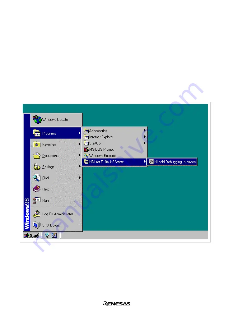
4. Power on the host computer and select [HDI for E10A H8Sxxxx] -> [Hitachi Debugging

Interface] from the [Start] menu.

Figure 2.5   [Start] Menu

Summary of Contents for H8S/2378F

Page 1: ...ok over all the business of both companies Therefore although the old company name remains in this document it is a valid Renesas Electronics document We appreciate your understanding Renesas Electron...

Page 2: ...t for an application categorized as Specific or for which the product is not intended where you have failed to obtain the prior written consent of Renesas Electronics The quality grade of each Renesas...

Page 3: ...tc Accordingly although Hitachi Hitachi Ltd Hitachi Semiconductors and other Hitachi brand names are mentioned in the document these names have in fact all been changed to Renesas Technology Corp Than...

Page 4: ...ed here may contain technical inaccuracies or typographical errors Renesas Technology Corporation assumes no responsibility for any damage liability or other loss rising from these inaccuracies or err...

Page 5: ...H8S 2378F E10A Emulator User s Manual User s Manual Rev 1 0 2002 10...

Page 6: ...f bodily injury such as aerospace aeronautics nuclear power combustion control transportation traffic safety equipment or medical equipment for life support 4 Design your application so that the produ...

Page 7: ...cations without consent of the appropriate officer of a Hitachi sales company Such use includes but is not limited to use in life support systems Buyers of this emulator product must notify the releva...

Page 8: ...chases the emulator product from you Hitachi is not liable for any claim made by a third party or made by you for a third party DISCLAIMER HITACHI MAKES NO WARRANTIES EITHER EXPRESS OR IMPLIED ORAL OR...

Page 9: ...any form in hard copy or machine readable form by any means available without Hitachi s prior written consent Other Important Things to Keep in Mind 1 Circuitry and other examples described herein are...

Page 10: ...mbol to avoid possible injury or death DANGER DANGER indicates an imminently hazardous situation which if not avoided will result in death or serious injury WARNING WARNING indicates a potentially haz...

Page 11: ...model the emulator product by yourself for electric shock prevention and quality assurance 2 Always switch OFF the host computer and user system before connecting or disconnecting any CABLES or PARTS...

Page 12: ...ill result in a FIRE HAZARD and will damage the user system and the emulator product or will result in PERSONAL INJURY The USER PROGRAM will be LOST CAUTION Place the host computer and user system so...

Page 13: ...when the equipment is operated in a commercial environment This equipment generates uses and can radiate radio frequency energy and if not installed and used in accordance with the instruction manual...

Page 14: ...VIII...

Page 15: ...emulators Section 6 describes supplements to the E10A emulator This manual consists of six sections The information contained in each section is summarized below Section 1 Overview gives the emulator...

Page 16: ...Corporation 2 Microsoft Windows and Windows NT are registered trademarks of Microsoft Corporation in the United States and or other countries Microsoft Windows 98 operating system is referred to as W...

Page 17: ...17 2 5 2 Writing H8S xxxx E10A Flash memory Mode 20 2 6 Ending the HDI 23 2 7 Uninstalling the HDI 24 Section 3 Tutorial 25 3 1 Introduction 25 3 2 Running the HDI 26 3 3 HDI Window 27 3 4 Setting up...

Page 18: ...indow 92 4 2 9 System Status Window 94 Section 5 Command line Functions 97 5 1 Table and Symbol Description 97 5 1 1 Format 97 5 1 2 Parameter Input 97 5 1 3 Examples 98 5 1 4 Related Items 98 5 2 Com...

Page 19: ...f the Hitachi UDI Port Connector 120 6 3 Differences between the MCUs and the Emulator 125 6 4 The H8S 2378F E10A Emulator Functions 126 6 4 1 Emulator Driver Selection 126 6 4 2 Hardware Break Functi...

Page 20: ...OMMUNICATION TIMEOUT ERROR Dialog Box 19 Figure 2 15 INVALID ASERAM FIRMWARE Dialog Box 19 Figure 2 16 Unable to restore the previous driver settings Dialog Box 20 Figure 2 17 System Clock Dialog Box...

Page 21: ...re 3 36 Point Page Break Dialog Box After Software Breakpoint Setting 54 Figure 3 37 Breakpoints Window Software Breakpoint Setting 55 Figure 3 38 Program Window at Execution Stop Software Break 55 Fi...

Page 22: ...13 System Status Window 94 Figure 6 1 Pin Arrangement of the Hitachi UDI Port Connector 120 Figure 6 2 Example of Emulator Connection 121 Figure 6 3 Connection of Emulator 122 Figure 6 4 EMLE Pin and...

Page 23: ...on Dialog Box Pages 88 Table 4 13 Address Group Box Options 90 Table 4 14 Radio Button Options 90 Table 4 15 Data Group Box Options 90 Table 4 16 Read Write Group Box Options 91 Table 4 17 Trace Windo...

Page 24: ...tions Set by BREAKCONDITION_SET Command 127 Table 6 8 Setting Trace Acquisition 129 Table 6 9 Items in the Trace Window 130 Table 6 10 Trace Search Function 131 Table 6 11 Address Group Box Options 13...

Page 25: ...similar to the actual application conditions The emulator enables debugging anywhere indoors or out The host computer for controlling the emulator must be an IBM PC compatible machine with a PCMCIA t...

Page 26: ...indows 2000 operating systems enable user program debugging using a pointing device such as a mouse The HDI enables high speed downloading of load module files Various debugging functions Various brea...

Page 27: ...rom excessive impacts and stresses For details refer to section 1 2 Environmental Conditions 4 Do not insert the emulator into any slot PCMCIA TYPE II slot or PCI slot other than the specified one 5 W...

Page 28: ...l be LOST Table 1 1 Environmental Conditions Item Specifications Temperature Operating 10 C to 35 C Storage 10 C to 50 C Humidity Operating 35 RH to 80 RH no condensation Storage 35 RH to 80 RH no con...

Page 29: ...uble of the load module size recommended Hard disk capacity Installation disk capacity 10 Mbytes or more Prepare an area at least double the memory capacity four times or more recommended as the swap...

Page 30: ...Components Check all the components unpacking For details on the E10A emulator components refer to section 6 1 Components of the Emulator If the components are not complete contact a Hitachi sales ag...

Page 31: ...use as follows Section 2 2 Section 2 3 Section 3 Unpack the emulator Check the components against the component list Turn on the host computer Install the HDI Start the HDI Turn on the user system Tur...

Page 32: ...ating system down and turn off the power to the host computer 3 Insert the PCI card emulator in a slot on the host computer Refer to section 2 3 Connecting the Host Computer with the Card Emulator 4 R...

Page 33: ...d log on with an administrator level user name 4 During HDI installation the setting value should be checked beforehand because inquiries are made about the resource used by the PCMCIA card emulator S...

Page 34: ...a PCMCIA card 1 Log on with an administrator level user name 2 Install the HDI When a component is selected be sure to select PC Card Driver PCMCIA 3 Insert the PCMCIA card emulator in the host comput...

Page 35: ...e to install the HDI before the card emulator is inserted Figure 2 2 Inserting the PCMCIA Card Emulator into the Host Computer Figure 2 3 Inserting the PCI Card Emulator into the Host Computer Use the...

Page 36: ...Specifications 2514 6002 3M Limited 14 pin straight type Note When the connector is used do not install any components within 3 mm of the connector 2 The pin arrangement of the connector is shown in...

Page 37: ...he user system interface cable from the user system pull the tab on the connector upward 3 The range of communications that the emulator operates at is different according to the MCUs used 4 Connect t...

Page 38: ...at the card emulator is inserted into the host computer 2 Connect the user system interface cable to the connector of the card emulator 3 Connect the user system interface cable to the Hitachi UDI por...

Page 39: ...15 5 Power on the user system and select the setting to be used Figure 2 6 Select Session Dialog Box...

Page 40: ...2 7 E10A Driver Details Dialog Box With the Driver combo box select the driver to connect the HDI with the emulator Interface displays the interface name of the card emulator to be connected and Chan...

Page 41: ...ry in the emulator Figure 2 8 System Clock Dialog Box 2 Set an eight digit hexadecimal ID code as a security code for the flash memory Input this ID code when H8S xxxx E10A Emulator is selected and th...

Page 42: ...r system during user program execution the following dialog box will be displayed Figure 2 11 H UDI Connector Disconnected Dialog Box 3 If the emulator is not initiated the following dialog boxes show...

Page 43: ...ystem is correctly connected Figure 2 13 Check the connection Dialog Box c If the following dialog box is displayed the MCU may not correctly operate Check if there are reasons for illegal MCU operati...

Page 44: ...the correct driver For details refer to section 6 4 1 Emulator Driver Selection 2 5 2 Writing H8S xxxx E10A Flash memory Mode In this mode the emulator is used as a flash memory writer The following...

Page 45: ...ck the Open button to start downloading Figure 2 18 Load Program Dialog Box 3 When the program has been downloaded the memory area that the checksum value and the program code have been written appear...

Page 46: ...iver setting must be incorrect Install a driver from the SETUP directory of the CD R according to the screen instructions 2 If the user system interface cable is disconnected from the connector on the...

Page 47: ...Exit HDI dialog box is displayed click the Yes button Figure 2 24 Exit HDI Dialog Box 2 Then the Save session dialog box is displayed If necessary click the Yes button to save session After saving se...

Page 48: ...n be changed modified or removed When the application is to be uninstalled select removal CAUTION A shared file may be detected while the program is being removed If another HDI may be using the share...

Page 49: ...al tutorial Debug tutorial abs Main program source file Installation directory tutorial tutorial tutorial c Stack information file Installation directory tutorial tutorial Debug tutorial sni Notes 1 T...

Page 50: ...3 2 Running the HDI To run the HDI select HDI for E10A H8Sxxxx Hitachi Debugging Interface from the Start menu Figure 3 1 Start Menu For the procedure of running the HDI refer to section 2 5 System Ch...

Page 51: ...user access to the HDI commands for using the HDI debugger 2 Toolbar Provides convenient buttons as shortcuts for the most frequently used menu commands 3 Program window Displays the source program be...

Page 52: ...w to set up the emulator for the tutorial programs 3 5 Setting the Configuration Dialog Box Select Configure Platform from the Setup menu to set configuration The Configuration dialog box is displayed...

Page 53: ...ecution default Step option Disables interrupt during single step execution Disables interrupts during single step execution default JTAG clock 4 125 MHz default Operating Mode Operating mode determin...

Page 54: ...d Program dialog box is displayed Enter the Offset edit box and File name list box as shown in figure 3 4 and click the Open button Figure 3 4 Load Program Dialog Box When the file has been loaded the...

Page 55: ...The HDI allows the user to debug a program at the source level Select Source from the View menu The Open dialog box is displayed Select the C source file that corresponds to the object file the user...

Page 56: ...Displaying the Source Program If necessary select the Font option from the Customize submenu on the Setup menu to select a clear font and size Initially the Program window shows the start of the main...

Page 57: ...re breakpoint at any point in a program For example to set a breakpoint at the sort function call Select by double clicking the BP column on the line containing the sort function call Figure 3 8 Progr...

Page 58: ...m counter PC double click the value area in the Registers window with the mouse The following dialog box is then displayed and the value can be changed Figure 3 10 Register Dialog Box PC Set the progr...

Page 59: ...ouble click the value area with the mouse The following dialog box is then displayed Figure 3 11 Register Dialog Box ER7 Set the value of the stack pointer to H FFFC00 in this tutorial program and cli...

Page 60: ...tton Or select Reset Go from the Run menu or click the Reset Go button on the toolbar Figure 3 13 Reset Go Button The program will be executed up to the breakpoint that has been inserted and a stateme...

Page 61: ...from the View menu After the System Status window is displayed open the Platform page and check the status of Cause of last break Figure 3 15 System Status Window Note The items that can be displayed...

Page 62: ...ays the execution status RUNNING Being executed Break Stopped Cause of last break Displays the cause of the emulator stopping at break In this example the cause of the stop is BREAK POINT Run time cou...

Page 63: ...he Breakpoints window Select Breakpoints from the View menu Figure 3 16 Breakpoints Window The pop up menu opened by clicking the Breakpoints window with the right mouse button also allows the user to...

Page 64: ...memory contents corresponding to the main in word size Select Memory from the View menu enter main in the Address edit box and set Word in the Format combo box Figure 3 17 Open Memory Window Dialog B...

Page 65: ...t a watch on the long type array a declared at the beginning of the program by using the following procedure Click the left of displayed array a in the Program window to position the cursor Click the...

Page 66: ...the Array The user can also add a variable to the Watch window by specifying its name Click the Watch window with the right mouse button and select Add Watch from the pop up menu The following dialog...

Page 67: ...ong type variable max Figure 3 22 Watch Window Displaying the Variable The user can double click the symbol to the left of any variable in the Watch window to watch the all elements in array a Figure...

Page 68: ...tion Menu Command Description Step In Executes each statement including statements within functions Step Over Executes a function call in a single step Step Out Steps out of a function and stops at th...

Page 69: ...t statement of the called function To step through the sort function select Step In from the Run menu or click the Step In button in the toolbar Figure 3 24 Step In Button Figure 3 25 Program Window S...

Page 70: ...ement of the calling statement in the main function To step out of the sort function select Step Out from the Run menu or click the Step Out button in the toolbar Figure 3 26 Step Out Button Figure 3...

Page 71: ...47 To execute two steps use Step In twice Figure 3 28 Program Window Step In Step In The value of max displayed in the Watch window is changed to the maximum data value...

Page 72: ...of the main program Using Step Over execute two steps to reach the change function statement Figure 3 29 Program Window Before Step Over Execution To step through all statements in the change function...

Page 73: ...49 Figure 3 31 Program Window Step Over When the last statement of the change function is executed the data of variable a which is displayed in the Watch window is sorted in descending order...

Page 74: ...layed Initially the Locals window is empty because local variables have not yet been declared Select Step In from the Run menu to execute a single step The Locals window will now show the local variab...

Page 75: ...Software Break Function The emulator can set up to 255 software breakpoints Setting a software breakpoint is described below Select Breakpoints from the View menu The Breakpoints window is displayed C...

Page 76: ...52 The Break dialog box is displayed The Point page is displayed as a default Figure 3 34 Point Page Break Dialog Box Click the Add button to display the Breakpoint dialog box...

Page 77: ...53 Enter H 10a4 to the Value edit box Figure 3 35 Breakpoint Dialog Box Click the OK button...

Page 78: ...54 The Break dialog box is displayed The address set in the value field of Breakpoint is displayed Figure 3 36 Point Page Break Dialog Box After Software Breakpoint Setting Click the Close button...

Page 79: ...reakpoints Window Software Breakpoint Setting To stop the tutorial program at the breakpoint the following procedure must be executed Close the Breakpoints window Click the Reset Go button The program...

Page 80: ...following contents Figure 3 39 Displayed Contents of the System Status Window Software Break Note The items that can be displayed in this window differ according to the product For the items that can...

Page 81: ...ons Select Breakpoint Window from the View menu The Breakpoints window is displayed Click the Breakpoints window with the right mouse button and select Delete All from the pop up menu to cancel all br...

Page 82: ...Condition Page Break Dialog Box Up to two breakpoints can be set independently for the hardware break condition In this example set the hardware break condition for Break condition 1 Note Note that t...

Page 83: ...ss after radio button and enter H 108C as the value in the Address edit box Figure 3 42 condition Page Break condition 1 Dialog Box Note The items that can be set in this window differ according to th...

Page 84: ...After Hardware Break Condition Setting Note Note that the number of hardware break conditions differs according to the product For the number that can be specified for each product refer to the on li...

Page 85: ...ed in Type in the Breakpoints window This completes the setting of the Break condition 1 hardware break condition When the program is executed a break will occur when address H 108C is accessed in a r...

Page 86: ...62 The program runs then stops at the condition specified under Break condition 1 Figure 3 45 Program Window at Execution Stop Break condition 1...

Page 87: ...following contents Figure 3 46 Displayed Contents of the System Status Window Break condition 1 Note The items that can be displayed in this window differ according to the product For the items that c...

Page 88: ...as shown in the example of section 3 15 1 Software Break Function The trace results are displayed in the Trace window after the program execution is completed Figure 3 47 Trace Window If necessary adj...

Page 89: ...out by using the emulation functions that the emulator offers This provides for effective investigation of hardware and software problems by accurately isolating and identifying the conditions under w...

Page 90: ...66...

Page 91: ...in this manual an O mark or the relevant section number is shown Related commands in the E10A Emulator User s Manual are also shown Table 4 1 HDI Window Menus and Related Manual Entries Menu Bar Pull...

Page 92: ...nd Line O Disassembly O I O Registers O Labels O Locals O 3 14 Memory O 3 11 Performance Analysis O Profile List O Profile Tree O Registers O 3 8 Source O 3 6 2 Status O 3 9 3 15 1 4 2 9 Trace O 4 2 8...

Page 93: ...ace User s Manual This Manual Memory Menu Refresh O Load O Save O Verify O Test O Fill O Copy O Compare O Setup Menu Status bar O Options O Radix O Customise O Configure Platform O 3 5 4 2 Window Menu...

Page 94: ...natory notes Read section 6 H8S xxxx E10A Emulator Specifications 4 2 1 Configuration Dialog Box Function This dialog box sets the emulation conditions of the emulator Window Figure 4 1 Configuration...

Page 95: ...ed in table 4 2 Table 4 2 Configuration Dialog Box Page Page Name Description General Sets the emulator operation conditions Clicking the OK button sets the emulation conditions If the Cancel button i...

Page 96: ...layed the emulation mode and interrupts during step execution are set the JTAG clock TCK is displayed and set and the driver is selected Window Figure 4 2 General Page Configuration Dialog Box Note Th...

Page 97: ...a waiting time will be generated to write the flash memory during user program halting but the displayed contents and the flash memory are always matched When synchronization is performed from the fl...

Page 98: ...displayed Figure 4 3 Warning Message Box When the Yes button is clicked the E10A Driver Details dialog box is displayed When the No button is clicked the display returns to the Configuration dialog bo...

Page 99: ...ed Figure 4 4 E10A Driver Details Dialog Box Table 4 4 shows each option Table 4 4 E10A Driver Details Dialog Box Option Option Description Driver combo box Selects the driver to connect the HDI with...

Page 100: ...inked up even if the above procedure has been executed the driver may not be set correctly Install drivers provided with the SETUP directory in the CD R according to the screen instructions Related It...

Page 101: ...pop up menu which is opened by clicking the right mouse button can be used to set change and clear breakpoints and to enable or disable break conditions The pop up menu functions are described in the...

Page 102: ...78 4 2 4 Break Dialog Box Function This dialog box displays the break condition settings Window Figure 4 6 Break Dialog Box...

Page 103: ...Box Pages Page Name Description Point Displays software breakpoint settings Condition Displays Break Condition settings The dialog boxes which set or modify break conditions can be displayed from the...

Page 104: ...80 1 Point Page Break Dialog Box Function This page displays software breakpoint settings In this page software breakpoints can be set changed and cleared Window Figure 4 7 Point Page Break Dialog Box...

Page 105: ...e Breakpoint dialog box Edit button Changes the software breakpoint selected in the Breakpoint list box Clicking this button displays the Breakpoint dialog box Reset button Clears the software breakpo...

Page 106: ...settings These conditions can also be set or cleared in this page Window Figure 4 8 Condition Page Break Dialog Box Note Note that the number of hardware break conditions differs according to the pro...

Page 107: ...mpty setting of Break condition 2 Edit button Changes the Break condition settings selected in the Break condition list box Clicking this button displays the Break condition dialog boxes Reset button...

Page 108: ...Function This dialog box sets software breakpoints Window Figure 4 9 Breakpoint Dialog Box Note The items that can be set in this window differ according to the product For the settings for each prod...

Page 109: ...box Sets a breakpoint address with a number or a symbol Clicking the OK button enables breakpoints to be set If the Cancel button is clicked this dialog box is closed without setting breakpoints Relat...

Page 110: ...ction This dialog box sets hardware break conditions Window Figure 4 10 Break condition 1 Dialog Box Note The items that can be set in this window differ according to the product For the settings for...

Page 111: ...escribed in section 4 2 7 Break condition Dialog Box Pages Clicking the OK button sets the hardware break conditions If the Cancel button is clicked the dialog box is closed without setting the hardwa...

Page 112: ...e Dialog Box Address Bus Condition Data Bus Condition Read Write Condition Break condition 1 dialog box O O O Break condition 2 dialog box O O O Note O Can be set by checking the radio button in the d...

Page 113: ...ge sets the address bus data bus and read write cycle conditions Window Figure 4 11 condition Page Note The items that can be set in this window differ according to the product For the settings for ea...

Page 114: ...condition is satisfied regardless of the address values The contents of an option that can be set will change depending on the radio button selected Table 4 14 Radio Button Options Option Description...

Page 115: ...ite radio button Sets the read write cycle conditions as break conditions Read radio button Sets read cycles as break conditions Write radio button Sets write cycles as break conditions Related Items...

Page 116: ...buffer contents The contents are displayed in both C and assembly languages to simplify debugging Window Figure 4 12 Trace Window Note This function differs according to the product For the number tha...

Page 117: ...truction operand Source Displays the C source line of the address that the trace has been acquired Total Records Displays the total number of instructions displayed as trace information in the Trace w...

Page 118: ...ion such as conditions that have been set to the emulator and execution results Window Figure 4 13 System Status Window Note The items that can be displayed in this window differ according to the prod...

Page 119: ...n status Displays the execution status Running Being executed Break Stopped Cause of last break Displays the cause of the emulator stopping at break Run time count Displays the program execution time...

Page 120: ...96...

Page 121: ...ts an exclusive selection The command parameter details are described in the parameter table 5 1 2 Parameter Input Numerical Parameters A binary octal decimal or hexadecimal value a symbol or a formul...

Page 122: ...examples For commands whose execution results in a specific display output an example of the display is given 5 1 4 Related Items Related E10A HDI commands abbreviations and dialog boxes are shown Re...

Page 123: ...isplays software breakpoints that have been set 8 BREAKPOINT_ENABLE BE Enables or disables software breakpoints that have been set 9 DEVICE_TYPE DE Displays MCU type currently selected 10 GO_OPTION GP...

Page 124: ...ts that have been set Format bcc channel channel channel channel_number Table 5 2 BREAKCONDITION_CLEAR Command Parameter Parameter Type Description None Examples To clear all hardware breakpoints bcc...

Page 125: ...ONDITION_DISPLAY Command Parameter Parameter Type Description None Examples To display all hardware breakpoint settings bcd RET Break Condition 1 Enable data 20 long Break Condition 2 Disable address...

Page 126: ...REAKCONDITION_ENABLE Command Parameter Parameter Type Description mode Keyword Enables or disables hardware breakpoint settings Set either of the following enable Enables hardware break settings disab...

Page 127: ...the MCUs used For functions of each emulator product refer to section 6 4 2 Hardware Break Functions Format bcs channel option option channel channel channel_number option addropt dataopt asidopt r w...

Page 128: ...bus during data access cycles are targeted maskdata Keyword Address bus mask conditions Conditions are satisfied regardless of the values of masked bits Set a radix H or B and set in the bit to be mas...

Page 129: ...address 1000 data 55 lbyte direction read RET To set the following conditions as a hardware breakpoint Address condition An address bus value of H 2000 and instruction fetch cycle bcs address 2000 pca...

Page 130: ...rameter Type Description address Numerical value character string Breakpoint value set by numerical value or symbol When an odd address is set the address is rounded down to an even address Note The p...

Page 131: ...l value character string Breakpoint value set by numerical value or symbol Note When no parameters are set all software breakpoints are cleared Note The parameters for this command vary with the produ...

Page 132: ...Parameter Parameter Type Description None Example To display the software breakpoints that have been set bd RET The display format is as follows bd H 00000110 Enable H 0000011c Disable H 00000250 Enab...

Page 133: ...sables breakpoints Set either of the following enable Enables breakpoints disable Disables breakpoints Examples To enable software breakpoints that have been set be H 1002 enable RET To disable softwa...

Page 134: ...n Displays MCU type currently selected Format de Table 5 10 DEVICE_TYPE Command Parameter Parameter Type Description None Example To display the currently selected MCU de RET The display format is as...

Page 135: ...no_break Makes software breakpoints and hardware breakpoints temporarily invalid and executes the user program Note The parameters for this command vary with the product For the specifications of eac...

Page 136: ...scription jck_opt Numerical value Sets one of the JTAG clock TCK frequency PCMCIA used 0 937 MHz 1 875 MHz 3 75 MHz 7 5 MHz or 15 MHz 1 15 MHz 2 7 5 MHz 3 3 75 MHz 4 1 875 MHz 5 0 937 MHz PCI used 1 0...

Page 137: ...TCK frequency JCK 1 RET JTAG Clock 15MHz To display the JTAG clock TCK frequency JCK RET JTAG Clock 15MHz when PCI used To set the JTAG clock TCK frequency JCK 1 RET JTAG Clock 16 5MHz To display the...

Page 138: ...REFRESH RF Description Updates the HDI memory information to the latest contents Format rf Table 5 13 REFRESH Command Parameter Parameter Type Description None Example To update the HDI memory informa...

Page 139: ...H8S xxxx The breakpoint settings are retained After the reset the registers will be in the same state as when power is supplied Format re Table 5 14 RESET Command Parameter Parameter Type Description...

Page 140: ...e emulator sts RET The display format is as follows sts Emulator Status Connected to H8S xxxx E10A Emulator E10A PC Card Driver 5 CPU H8S xxxx Run status Break Cause of last break BREAK KEY Run time c...

Page 141: ...rrupts during step execution si mode Sets the enable or disable status of interrupts during step execution Table 5 16 STEP_INTERRUPT Command Parameter Parameter Type Description mode Keyword Enables o...

Page 142: ...n None Example To display acquired trace information td RET The display format is as follows td IP TYPE ADDR MNEMONIC OPERAND D xxxx BRANCH 00001010 JSR ER0 D xxxx BRANCH 00001200 JMP ER1 a b c d e a...

Page 143: ...mulator HS2378KCM01H Model HS0005KCM05H HS2378KCI01H Model HS0005KCI05H PC PC Card or 1 HS2378KCM01H PCMCIA 14 pin type Depth 85 6 mm Width 54 0 mm Height 5 0 mm Mass 30 0 g HS2378KCI01H PCI 14 pin ty...

Page 144: ...or 1 pin 8 pin 7 pin 14 pin Pin No Signal 1 2 3 4 5 6 7 8 to 10 12 to 14 11 Note 1 Input or output from the user system 2 The symbol means that the signal is active low 3 By detecting GND on the user...

Page 145: ...signals to the MCU An AND operation must be performed between RES pin 4 and the user system reset circuit for the signal line connected to the MCU RES of pin 7 of the Hitachi UDI port connector is a s...

Page 146: ...t connector 4 7 k H8S 2377F H8S 2367F Pins 1 2 3 5 and 6 Vcc Figure 6 3 Connection of Emulator 2 The EMLE pin in the H8S 2377F and H8S 2367F must be pulled up when connecting with the emulator and con...

Page 147: ...in the Hitachi UDI port connector to GND in the user system 5 Connect Vcc pin 11 in the Hitachi UDI port connector to the power supply Vcc in the user system The amount of voltage permitted to input...

Page 148: ...e following pin functions cannot be used Table 6 2 Unavailable Pin Functions H8S 2377F H8S 2367F P53 and PG4 to PG6 P53 and PG4 to PG6 WDTOVF WDTOVF IRQ3 IRQ3 ADTRG ADTRG BREQ BACK and BREQ0 BREQ BACK...

Page 149: ...the system control register The emulator saves the register value of the system control register at a break and returns the value when the user program is executed Since this is done during a break d...

Page 150: ...Name Driver HS2378KCM01H E10A PC Card Driver 5 HS2378KCI01H E10A PCI Card Driver 5 6 4 2 Hardware Break Functions Hardware Break Conditions In the H8S 2378F E10A emulator two break conditions can be...

Page 151: ...ommand Condition Channel Address Bus Condition addropt option Data Condition dataopt option Read or write condition r wopt option Break condition 1 O O O Break condition 2 O O O Note O Can be set by t...

Page 152: ...a software breakpoint is disabled 4 A condition set at Break Condition is disabled immediately after starting execution when an instruction at a software breakpoint is executed A break does not occur...

Page 153: ...type Sets the trace information for acquisition and display Branch trace Acquires and displays the branch instruction trace information Bus trace Acquires and displays the bus trace information Bus t...

Page 154: ...on instruction Data The value of the data bus R W Type of the read write signal RD read cycle WT write cycle Area Type of the access area ROM ROM area RAM RAM area IO 8 8 bit I O IO 16 16 bit I O EXT...

Page 155: ...ddress Group Box Options Option Description Don t care check box Indicates that no address condition is set Address radio button Sets an address as a display condition Range radio button Sets an addre...

Page 156: ...M area as a display condition IO 8 check box Sets an 8 bit I O area as a display condition IO 16 check box Sets a 16 bit I O area as a display condition EXT 8 check box Sets an 8 bit external area as...

Page 157: ...played in the Trace window Table 6 17 Commands for the Trace Function Command Name Description TRACE_DISPLAY Displays the acquired trace information TRACE_MODE Displays or sets the acquisition mode of...

Page 158: ...isplay format of the bus trace information is as follows td start 10 end 5 CYCLE ADDRESS LABEL MNEMONIC OPERAND DATA R W AREA STATUS CLOCK IRQ D 0010 00FF600C MOV B ER1 R4L 681C RD RAM PROG 1 0 D 0009...

Page 159: ...TRACE_MODE Command Parameter Parameter Type Description type Keyword Sets a type of traces to be acquired branch Acquires the branch trace bus Acquires the bus trace mode Keyword full Acquires the bus...

Page 160: ...36 Example To disable acquiring the DMAC cycle in the bus trace tm type bus cycle dmac RET The display format of the setting state of the trace acquisition mode is as follows tm RET type bus cycle dma...

Page 161: ...ays the trace information with the specified condition Format ts addropt dataopt statusopt areaopt rwopt irqopt fromopt addropt address address dataopt data data size statusopt status status areaopt a...

Page 162: ...condition refresh The refresh cycle is the search condition area Keyword Sets the area condition rom The ROM area is the search condition ram The RAM area is the search condition io 8 The IO 8 area is...

Page 163: ...xxxx xxxxx x x D 0074 xxxxxxxx xxx xxxxx xxx xxxx xx xxxx xxxxx x x D 0073 xxxxxxxx xxx xxxxx xxx xxxx xx xxxx xxxxx x x D 0072 xxxxxxxx xxx xxxxx xxx xxxx xx xxxx xxxxx x x D 0071 xxxxxxxx xxx xxxxx...

Page 164: ...e to the next line execute two steps 3 Operation During Accessing Files Do not perform other operations during saving in the Load Program Verify Memory Save Memory or Trace window because this will no...

Page 165: ...e debugging information file after all the load modules have been loaded 7 Line Assembly Input radix Regardless of the Radix setting the default for line assembly input is decimal Specify H or 0x as t...

Page 166: ...used debug platform name 11 Select Function dialog box This HDI does not support software breakpoint setting in the Select Function dialog box described in section 10 Selecting Functions in the Hitach...

Page 167: ...as been input in the Register dialog box the Radix setting is changed to hexadecimal When the radix other than a hexadecimal is used as a default reset the Radix display 19 Software Break Session file...

Page 168: ...fter downloading the program perform verify in the Verify S Record File with Memory dialog box which is opened when Verify is selected from the Memory menu 24 Support of Double Float Format In the fol...

Page 169: ...est Memory Compare View Performance Analysis Memory Configure Map Memory Configure Overlay and Trace popup menu options Halt Restart and Snapshot 31 Memory Access during Emulation When a memory is acc...

Page 170: ...the WDT continues operation during a break When a counter value overflows during a break in the watchdog timer mode An internal reset signal is generated when the internal LSI is reset When a counter...

Reviews: