7
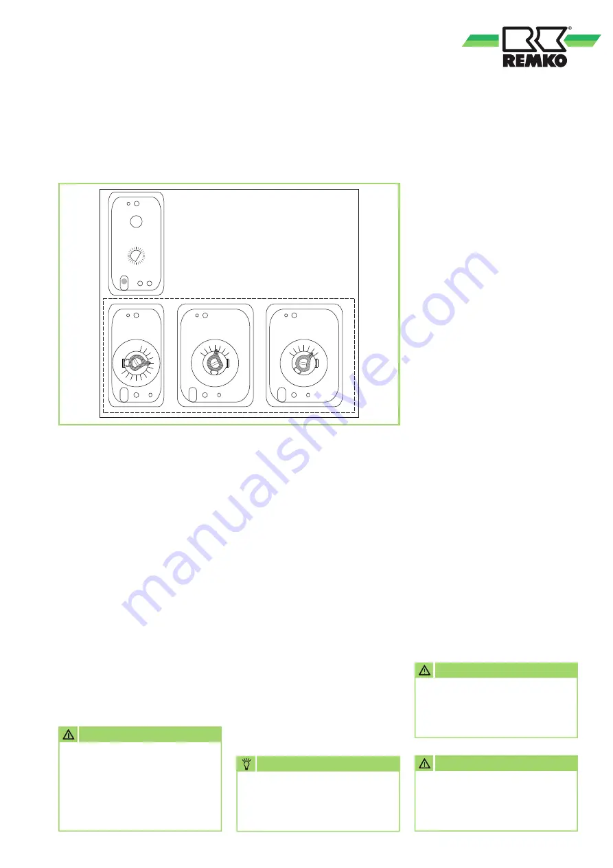
The 4 functions of the
controller unit:
1.
Fan controller (TR)
Controls the switching on and
off of the fan. The switching
point is set via the "setting lever
TR".
Setpoint value approx. 40°C
2.
Temperature monitor for
the burner (TW 2)
The temperature monitor limits
the discharge temperature.
The switching point is set via
the "setting lever TW 2".
Setpoint value approx. 75 – 80°C
3.
Temperature switch for
the second stage of the burner
(TW 1)
The temperature switch controls
the stage of the burner.
If the set temperature is
exceeded, the burner is
switched to the lower stage
(partial load operation). The
switching point is set via the
"setting lever TW1". Setpoint
approx. 10-15 K below TW2
4.
Safety
thermal cut-out (STB)
Takes over the control function
of the temperature monitor.
Switching point fixed at 100°C.
A restart interlock prevents the
burner from restarting after
tripping. The reset button
(RESET) must be operated
manually from the outside with
the housing cover closed.
Thecontroller unit
has a probe
self-monitoring and is cold-proof
down to -20°C. The unit switches
off below -20°C, but switches on
again when the temperature rises
and is then fully functional.
In the event of the probe or the
capillary tube being damaged, as
well as if a temperature of ap-
prox. 220°C is reached, the filling
medium will be emptied and the
controller unit will switch off for
safety. The controller unit is no
longer fully functional and must be
replaced.
To replace the controller unit, ob-
serve the following instructions,
among others:
■
The capillary tubes must not
be damaged or kinked during
installation
■
Bends may only be made on
the capillary tube and not on
the probe
■
For safe operation of the unit,
the probes must always be
exposed in the hot air flow
■
The probes must always be free
of dust and dirt
■
Capillary tubes and probes must
not show any damage
■
The probes must not be in
contact with the combustion
chamber
Controller unit per DIN EN 14597
Oil-fired or gas-fired warm air heaters must be equipped with intrinsically
safe control devices in accordance with DIN EN 14597.
70
80
60
°C
TW1
50
STB
20
80
70 60
50
40
30
°C
TR
70
80
60
°C
TW2
50
NOTE
When replacing the controller
unit, only an original REMKO
spare part may be used!
CAUTION
In order to prevent a renewed
exceedance of the triggering
temperature the operating
conditions of the unit should
be checked before resetting
the STB.
CAUTION
Safety devices may not be
bypassed or disabled during
unit operation!
CAUTION
Careful and professional
installation or assembly must
be ensured.


