REMKO RT 080 Operator'S Manual Download Page 28

27

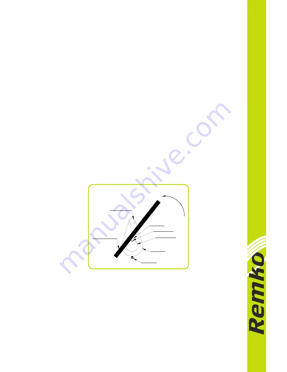
Figure 12. Loosening impeller

(Figure 10, Page 21)

Remove the hardware (13 and 14) securing the rotating assembly to the pump casing. 
Separate the Rotating assembly by pulling straight away from the pump casing.

NOTE:  

An optional disassembly tool is available from the factory. If the tool is 

used, follow the instructions packed with it. A similar tool may be assembled 
using ½ inch pipe (schedule 80 steel or malleable iron) and a standard tee (see 
Figure 13, Page 27). All threads are ½ inch NPT. Do not pre-assemble the tool.


 Turn


Counterclockwise


Lathe Dog Arm


Heavy Bar Stock


Set Screw


Lathe Dog 


Impeller Shaft


Shaft Keyway


"V" Notch


NOTE:  

Further disassembly of the check valve is not required since it must be 

replaced as a complete unit. Individual parts are not sold separately.

Rotating Assembly Removal

(Figure 11, Page 23)

The rotating assembly may be serviced without disconnecting the suction or discharge 
piping; however, the power source must remove to provide clearance.

The impeller (1) should be loosened while the rotating assembly is still secured to the 
pump casing. Before loosening the impeller, remove the seal cavity drain plug (24) and 
drain the seal lubricant. This will prevent the oil in the seal cavity from escaping when 
the impeller is loosened. Clean and reinstall the seal cavity drain plug.

Immobilize the impeller by wedging a wood block between the vanes and the pump 
casing, and remove the impeller cap screw and washer (10 and 12).

Install a lathe dog on the drive end of the shaft (17) with the “V” notch positioned over 
the shaft keyway.

With the impeller rotation still blocked, see Figure 12 below and use a long piece of 
heavy bar stock to pry against the arm of the lathe dog in a counterclockwise direction 
(when  facing  the  drive  end  of  the  shaft). 

Use  caution

  not  to  damage  the  shaft  or 

keyway. When the impeller breaks loose, remove the lathe dog and wood block.

NOTE:   

Do not remove the impeller until the rotating assembly has been removed 

from the pump casing.

Summary of Contents for RT 080

Page 1: ...OPERATORS MANUAL Installation Operation Maintenance and Parts List RT 080...

Page 2: ...ALVE Theory of Operation Air Release Valve Installation 7 ALIGNMENT Coupled Drivers V Belt Drives SECTION C OPERATION 8 PRIMING 9 STARTING Rotation 10 OPERATION Lines With a Bypass Lines Without a Byp...

Page 3: ...Seal and Installation Impeller Installation Rotating Assembly Installation Suction Check Valve Installation Back Cover Installation 15 PRESSURE RELIEF VALVE MAINTENANCE Final Pump Assembly 16 LUBRICAT...

Page 4: ...butor For information or technical assistance on the power source contact the power source manufacture s local dealer or representative The following are used to alert maintenance personnel to procedu...

Page 5: ...epair and with adequate capacity to prevent injuries to personnel or damage to equipment Suction and discharge hoses and piping must be removed before lifting Do not remove plates covers gauges pipe p...

Page 6: ...supplied to the pump under pressure some of the information such as mounting line configuration and priming must be tailored to the specific application Since the pressure supplied to the pump is cri...

Page 7: ...ns used to lift and move the unit is improperly wrapped around the pump CAUTION Mounting Locate the pump in an accessible place as close as practical to the liquid being pumped Level mounting is essen...

Page 8: ...acuum suction gauges If these gauges are desired for pumps that are not tapped drill and tap the suction and discharge lines not less than 500mm from the suction and discharge ports and install the li...

Page 9: ...nded Suction inlet at a distance 1 times the diameter of the suction pipe The baffle will allow entrained air to escape from the liquid before it is drawn into the suction inlet If two suction lines a...

Page 10: ...The bypass line should be sized so that it does not affect pump discharge capacity however the bypass line should be at least 25mm in diameter to minimize the chance of plugging In low discharge head...

Page 11: ...anual shut off valve may cause a pump which has lost prime to continue to operate without reaching prime causing dangerous overheating and possible explosive rupture of the pump casing Personnel could...

Page 12: ...ion about anAutomaticAir Release Valve for your specific application Air Release Valve installation The Automatic Air Release Valve must be independently mounted in a horizontal position and connected...

Page 13: ...nted so that their shafts are aligned with and parallel to each other It is imperative that alignment be checked after the pump and piping are installed and before operation NOTE Check Rotation Sectio...

Page 14: ...at the pulleys are properly aligned see Figure 8 below In drive systems using two pr more belts make certain that the belts are a matched set unmatched sets will cause accelerated belt wear Figure 6 A...

Page 15: ...is designed to handle mild industrial corrosives mud or slurries containing large entrained solids Do not attempt to pump volatile corrosive or flammable liquids which may damage the pump or endanger...

Page 16: ...tion of pump rotation is counterclockwise when facing the impeller The pump could be damaged and performance adversely affected by incorrect rotation If pump performance is not within the specified li...

Page 17: ...each overhaul or any time the pump casing overheats and activates the valve Never replace this valve with a substitute which has not been specified or provided by Remko Strainer Check If a suction st...

Page 18: ...ngine driven pumps reduce the throttle speed slowly and allow the engine to idle briefly before stopping If the application involves a high discharge head gradually close the discharge throttling valv...

Page 19: ...sing See PRIMING Clean or replace check valve Correct leak Replace suction hose Check pump vacuum Replace leaking or worn seal or gasket Check piping installation and install bypass line if needed See...

Page 20: ...nding Correct leak Replace suction hose Check pump vacuum Replace leaking or worn seal or gasket Check strainer and clean if necessary Check installation and correct sub mergence as needed Replace wor...

Page 21: ...e and impeller trim 13 PERFORMANCE CURVE Pump speed and operating condition points must be within the continuous performance range shown on the curve CAUTION Figure 9 Pump Performance Curve NPSH Net P...

Page 22: ...21 SECTION DRAWING Figure 10 Pump Model...

Page 23: ...VER PLATE WARNING PLATE DRIVE SCREW 41 02 BACK COVER HANDLE 42 04 HEX HEAD CAPSCREW 43 04 LOCKWASHER REPAIR ROTATING ASSEMBLY DISCHARGE FLANGE GASKET VALVE ASSEMBLY WEAR PLATE O RING BACK COVER SUCTIO...

Page 24: ...23 SECTION DRAWING DRIVE END VIEW SEAL AREA DETAIL Figure 11 Repair Rotating Assembly...

Page 25: ...21 22 23 24 25 26 27 28 01 01 01 01 01 01 01 01 01 01 01 01 04 04 01 01 01 01 01 01 01 01 01 01 04 04 01 01 PART NUMBER PART NUMBER T080 RO 01 CI T080 RO 02 T080 RO 03 T080 RO 04 T080 RO 05 T080 RO 0...

Page 26: ...rge Flange Gasket Suction Flange Gasket BEARING KITS RT080 Includes Bearing Cap Gasket Seal Plate Gasket Inboard Oil Seal Outboard Oil Seal Inboard Ball Bearing Outboard Ball Bearing IMPELLER ADJUSTIN...

Page 27: ...the pump 1 Familiarize yourself with this manual 2 Disconnect or lock out the power source to ensure that the pump will remain inoperative 3 Allow the pump to cool if overheated 4 Check the temperatur...

Page 28: ...n or discharge piping however the power source must remove to provide clearance The impeller 1 should be loosened while the rotating assembly is still secured to the pump casing Before loosening the i...

Page 29: ...e shims or measure and record their thickness for ease of reassembly Seal Removal Figure 11 Page 23 Slide the integral shaft sleeve and rotating portion of the seal off the shaft as unit Use a pair of...

Page 30: ...ammable Use them only in a well ventilated area free form excessive heat sparks and flame Read and follow all precautions printed on solvent containers WARNING Clean the bearings thoroughly in fresh c...

Page 31: ...ickly in one continuous motion to prevent the bearings from cooling and sticking on the shaft After the bearings have been installed and allowed to cool check to ensure that they have not moved away f...

Page 32: ...o damage the oil seal lip on the shaft keyway Lubricate the bearing housing as indicated in LUBRICATION Seal Installation Figures 11 pg 23 14 below 15 pg 31 and 16 pg 31 Most cleaning solvents are tox...

Page 33: ...eller to seal plate clearance and remove impeller adjusting shims to obtain the proper clearance as described Impeller Installation and Adjustment If necessary to reuse an old seal in an emergency car...

Page 34: ...them could damage the bellows CAUTION The shaft and impeller threads must be completely clean before reinstalling the impeller Even the slightest amount of dirt on the threads can cause the impeller...

Page 35: ...removed Secure the rotating assembly to the pump casing with the hardware 13 and 14 Do not fully tighten the cap screw until the back cover has been set A clearance of 0 25 to 0 51mm between the impe...

Page 36: ...o Liquid Temperature And Overheating in OPERATION It is recommended that the pressure relief valve assembly be replaced at each overhaul or any time the pump overheats and activates the valve Never re...

Page 37: ...to overheat resulting in premature bearing failure NOTE The white reflector in the sight gauge must be positioned horizontally to provide proper drainage Under normal conditions drain the bearing hou...

Page 38: ...37 NOTES...

Page 39: ...o of such as part as shall appear to us upon inspection at such point to have been defective in material or workmanship This Warranty does not obligate Remko to bear the cost of labour or transportati...

Page 40: ...1800 333 424...

Reviews: