12
REMKO PGM (E) series
Gas burner
Unit type
A
B
C
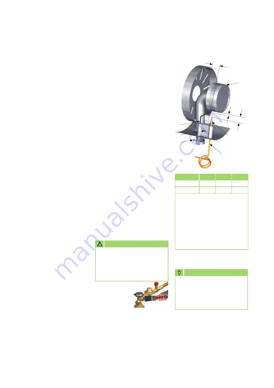
PGM 30 approx. 3 approx. 15 approx. 20
PGM 60 approx. 3 approx. 15 approx. 35
All dimensions in mm
Legend:
1 = Gas burner
2 = Thermocouple
3 = Capillary tube
(fixed component of the thermocouple)
4 = Ignition electrode
5 = Clamping screw
(electrodes)
6 = Clamping screw
(gas nozzle)
Disassembling and cleaning
the gas burner
1. Switch off the gas supply
to the unit and remove the
power plug from the mains
socket.
2. Remove the protective outlet
grille, exterior cladding and
inspection cover.
3. Undo the clamping screw 6
of the nozzle holder.
4. Remove the ignition cable from
the ignition electrode 4.
5. Detach the capillary tube 3
of the thermocouple from the
safety pilot.
6. Loosen the clamping screw 5
on the electrode bracket and
carefully draw out the ignition
electrode.
7. Carefully pull the thermocouple
with capillary tube down and
out.
Be aware of the extremely
sensitive capillary tube here!
8. Carefully remove any adhered
deposits from the ignition
electrode and thermocouple.
9. Detach the fastening screws
of the gas burner and remove
the complete gas burner from
the unit.
10. Carefully clean the gas burner
with a suitable brush and
possibly compressed air.
11. Clean the gas nozzle
if necessary.
Do not use any sharp-edged
objects!
12. Carefully remove deposits
or soiling in the unit base.
13. After all cleaning work on
the gas burner, carefully refit
all parts in reverse order.
14. After using the gas nozzle,
tighten the clamping screw 6
again.
15. Adjust the ignition
electrode and thermocouple
in accordance with the sketch
and tighten the clamping
screw 5 of the electrode
bracket.
16. Carefully refit all parts
of the unit in reverse order.
1
5
2
4
6
A
B
C
3
for example with:
Soap solution or
leak detection
spray.
NOTE
A strongly yellowy flame
indicates an inadequate
fresh air supply or dirt inside
the unit.
CAUTION
A functional inspection of
the entire unit including leak
testing of all gas-conveying
connections must be
conducted


