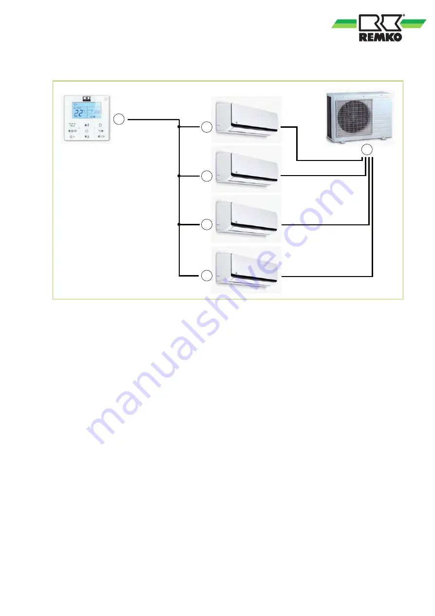
Variant 3: Assembly of a multi-split combination with a remote control
A
C
B
Fig. 7: Assembly of a multi-split combination with a remote control
A: KFB 3
B: MVT 1051 DC
C: MXW 262
13
Page 1: ...Assembly and operating instructions Read the instructions prior to performing any task REMKO KFB 3 Wired remote control RVD DC RVT DC RXT DC MXD MXT MVD and MVW 0061 2013 09 Edition 1 en_GB...
Page 2: ...g inal Read these operating instructions carefully before commis sioning using this device These instructions are an integral part of the system and must always be kept near or on the device Subject t...
Page 3: ...es for installation maintenance and inspection 5 1 8 Unauthorised modification and changes 5 1 9 Intended use 5 1 10 Warranty 5 1 11 Transport and packaging 6 1 12 Environmental protection and recycli...
Page 4: ...y be fatal or cause serious injury WARNING This combination of symbol and signal word warns of a potentially hazardous situation which if not avoided may be fatal or cause serious injury CAUTION This...
Page 5: ...ly be secured or mounted on stable structures walls or floors n Mobile units must be set up securely on suit able surfaces and in an upright position Sta tionary units must be permanently installed fo...
Page 6: ...on and recycling Disposal of packaging All products are packed for transport in environ mentally friendly materials Make a valuable contri bution to reducing waste and sustaining raw mate rials Only d...
Page 7: ...mensions height width depth mm 120 120 20 Weight kg 0 2 Max cable length m 15 Recommended cable mm2 4 x 0 5 We reserve the right to modify the dimensions and design as part of the ongoing technical de...
Page 8: ...ure is 1 C above the desired temperature and sufficient coolant is available the indoor unit will start to cool the room air If the actual temperature falls approx 0 5 C below the set room temperature...
Page 9: ...wired remote control The symbol appears on the display when you press the and keys simultaneously The wired remote control is now locked and is unre sponsive when keys are pressed The device no longer...
Page 10: ...d is not affected by any sources of heat or cold 5 Make the connections in accordance with the electrical circuit diagram Electric connec tions must be carried out as fixed connec tions in accordance...
Page 11: ...D E 3 Fig 4 Electrical wiring diagram 1 Wired remote control 2 Indoor unit 3 On site extension by way of a four core cable max 15m Colour coding Wired remote control 1 A Blue B Gray C Red D Black Col...
Page 12: ...f a single split combination with a remote control A KFB 3 B RVT 262 DC AT C RVT 262 DC IT Variant 2 Assembly of two single split combinations with a remote control e g server room A B C B C Fig 6 Ass...
Page 13: ...Variant 3 Assembly of a multi split combination with a remote control A C C C C B Fig 7 Assembly of a multi split combination with a remote control A KFB 3 B MVT 1051 DC C MXW 262 13...
Page 14: ...rating range 7 Operation 8 P Power supply 7 R Recirculation mode 8 Removing the housing cover 9 S Safety Dangers of failure to observe the safety notes 4 General 4 Identification of notes 4 Notes for...
Page 15: ......
Page 16: ...t as advisers to our customers in air conditioning and heating technology SFlbCustomer Service Our equipment operates precisely and reliably However in the event of a fault REMKO customer service is q...