6
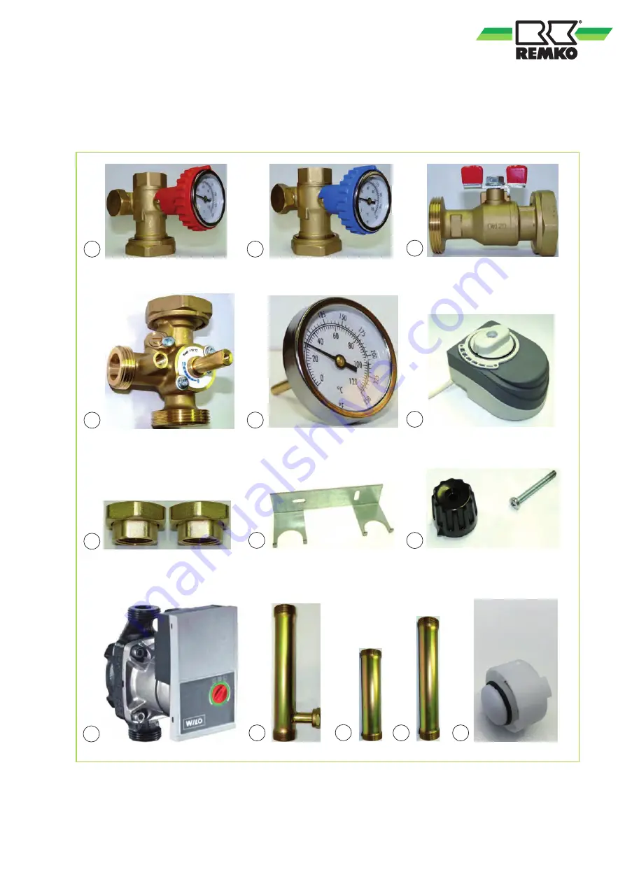
Spare parts list for pump groups HGM / HGU
Spare parts illustration
2
1
9
3
4
5
7
8
10
11
13
12
14
We reserve the right to modify the dimensions and design as part of the ongoing technical development
process
25
Page 1: ...Assembly and operating instructions Read the instructions prior to performing any task REMKO PUMP GROUPS HGM HGU Instructions for the Technician 0041 2017 11 Edition 2 en_GB...
Page 2: ...g inal Read these operating instructions carefully before commis sioning using this device These instructions are an integral part of the system and must always be kept near or on the device Subject t...
Page 3: ...data for pump groups HGM HGU 7 2 2 Unit dimensions and pump group components HGM 8 2 3 Unit dimensions and pump group components HGU 9 2 4 Pump unit data 10 2 5 Pump unit dimensions 11 2 6 Pressure lo...
Page 4: ...tal or cause serious injury WARNING This combination of symbol and signal word warns of a potentially hazardous situation which if not avoided may be fatal or cause serious injury CAUTION This combina...
Page 5: ...cation and changes The operational safety of the pump group that was delivered is guaranteed only with intended use in accordance with section 1 9 of the operating instructions Under no circumstances...
Page 6: ...isposing of packaging All products are packed for transport in environ mentally friendly materials Make a valuable contri bution to reducing waste and sustaining raw mate rials Only dispose of packagi...
Page 7: ...lycol mixture maximum 30 Thermometer measurement range 0 120 C 30 250 F Weight kg 6 9 5 85 Materials Pump group HGM HGU Ball valve and check valve Body made of brass UNI EN 12164 CW617N UNI EN 12164 C...
Page 8: ...roup G G1 L H HGM 1 IG 1 1 2 AG 125 mm 363 mm Components 2 1 4 3 6 7 5 4 1 2 5 3 4 Fig 2 Pump group components HGM 1 Circulation pump Wilo Stratos Para 25 1 7 T1 2 Ball valve 3 Ball valve with integra...
Page 9: ...ns for pump group HGU Pump group G G1 L H HGU 1 F 1 1 2 M 125 mm 363 mm Components 2 1 4 3 6 5 4 1 2 3 4 Fig 4 Pump group components HGU 1 Circulation pump Wilo Stratos Para 25 1 7 T1 2 Ball valve 3 B...
Page 10: ...ambient temperature C 40 Maximum relative humidity 95 Permitted conveying media Heating water in accordance with VDI 2035 VdT V Tch 1466 Water Glycol mixture maximum mixture ratio is 1 1 in mixtures w...
Page 11: ...5 Dimensions in mm 180 116 32 94 90 56 138 42 41 2 6 Pressure losses 2 1 A B A m3 h B m3 h mbar mbar a a Fig 6 Diagram of pressure losses in the pump group HGM HGU 1 Operational mode constant differen...
Page 12: ...or inlet and return flow check valve against the heating cycle and thermal insulation The pump group HGM also has an integrated mixing valve The pump group with the heating cycle mixing valve consists...
Page 13: ...stallation n Installation on the distributor 4 2 Wall installation CAUTION You must adhere to the distance between the piping and the wall specified in point 7 1 Remove the pre installed pump group fr...
Page 14: ...re suitable for the pipe dimensions connections with flat seals are recom mended If a pump is connected in a series to the pump group e g boiler pump in prac tice a fixture to separate the heating cyc...
Page 15: ...ut installation steps 1 4 for wall installation 2 To aid installation start the installation in the middle of the distributor and then continue with the outer connections install the inlet 4 and the r...
Page 16: ...the front part of the insulation 1 2 1 4 4 Positioning of the electric cables The electric cables must be installed by qualified personnel in order to avoid endangering people s safety and material d...
Page 17: ...changes to the turning direction of the motor Attention If there are large temperature differences between the temperature in the buffer tank and the temperature in the heating cycle it is possible th...
Page 18: ...shown in the diagram 2 4 3 5 1 Fig 9 Installation of the actuator 1 Actuator 2 Ring with scale 3 Adapter for the mixing valve 5 Screw for fixing the drive 1 The ring with scale 2 is the reference poin...
Page 19: ...g cycle circulation pump on the regulator of the heat pump You can obtain information about the terminal connections from the installation instructions of the heat pump in the Terminal connec tions le...
Page 20: ...eans that the pump is on the right and the inlet on the top The heating cycle group can be configured using the process shown in diagrams 2 3 and 4 1 Loosen the rotary valves see the arrow and uncoupl...
Page 21: ...ting cycle floor bl br sw L X N PE A41 GND SMTIO A41 Pump 0 10V 1 M U N A41 Pump Heating cycle floor Power supply A41 br bl gnge ws br L X N PE A42 GND SMTIO A42 Pump 0 10V 1 M U N A42 Pump Heating cy...
Page 22: ...30 V Unregulated 230 V Fig 12 Connection terminals for installing unregulated circulation pump heating cycles 4 10 Installation example A B C D B AB A HGM HGU KK HK FB Fig 13 Example hydraulic diagram...
Page 23: ...Overload error is reported The motor is stopped and started again after a 30 second pause If no overloading occurs within the next 2 minutes the internal error counter is reset Otherwise the motor is...
Page 24: ...d off permanently This can only be reset by switching the power off for more than 30 seconds The SSM relay is active as long as the internal error counter is not ZERO Cable break Control is defec tive...
Page 25: ...parts list for pump groups HGM HGU Spare parts illustration 2 1 9 3 4 5 7 8 10 6 11 13 12 14 We reserve the right to modify the dimensions and design as part of the ongoing technical development proc...
Page 26: ...g valve with three point regu lator speed 120s 90 turning angle 90 torque 10 Nm voltage 230V frequency 50Hz Com plete with locking screw and pin to fix the actuator Speed 120 s 90 Controller 3 point 1...
Page 27: ...Packaging disposal 6 Positioning of the electric cables 16 Pressure losses 11 Pump group layout 20 Pump group materials 7 R Recycling 6 Replace the pump 19 Replacement of the pump 19 S Safety Dangers...
Page 28: ...t as advisers to our customers in air conditioning and heating technology SFlbCustomer Service Our equipment operates precisely and reliably However in the event of a fault REMKO customer service is q...